Hyundai Ioniq (AE): AHB(Active Hydraulic Boost) System / Brake Actuation Unit. Repair procedures
Hyundai Ioniq (AE) 2017-2022 Service & Repair Manual / Brake System / AHB(Active Hydraulic Boost) System / Brake Actuation Unit. Repair procedures
| Removal |
| 1. | Turn ignition switch OFF and disconnect the negative (-) battery cable. |
| 2. | Disconnector TCM connector (A). |
| 3. | Disconnector TCM connector (B).
|
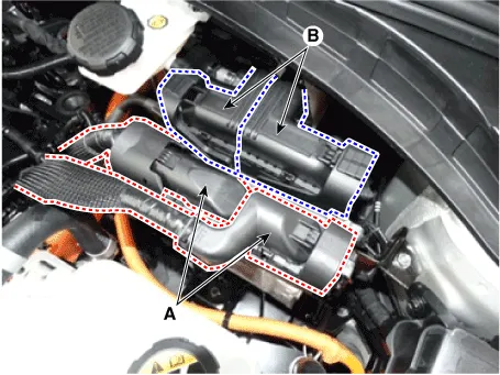
| 4. | Loosen the bolt & nut (A) then remove the ECM, TCM with bracket (B).
|
| 5. | Remove the air cleaner. (Refer to Engine Mechanical System - "Air Cleaner") |
| 6. | In case of RHD vehicle, remove the engine and transmission assembly. (Refer to Engine Mechanical System - "Engine and Transmission Assembly") |
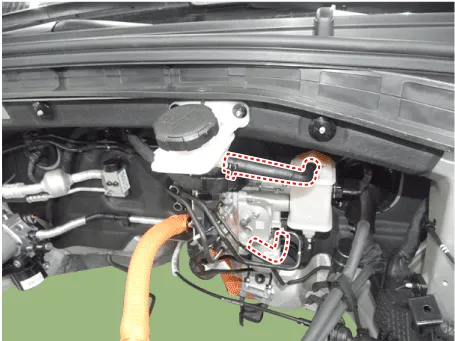
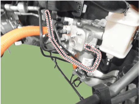
| 7. | Remove the brake fluid from the reservoir with a syringe.
|

| 8. | Disconnect the brake hose from the reservoir.
|
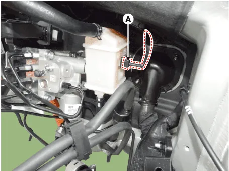
| 9. | Disconnect the brake fluid level switch connector (A).
|
| 10. | Disconnect IBAU connecter.
|
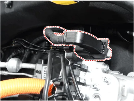
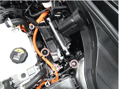
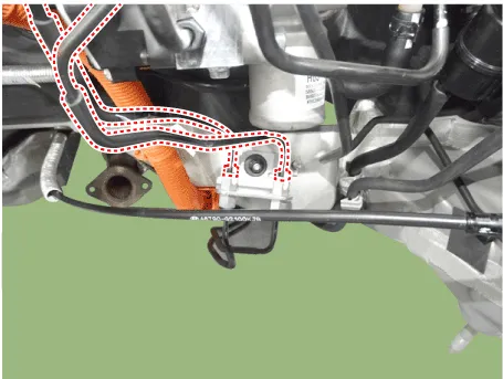
| 11. | Disconnect the brake tube from the IBAU (Intergrated Brake Actuation Unit) by loosening the tube flare nut.
|

| 12. | Disconnect the brake tube from the IBAU (Intergrated Brake Actuation Unit) by loosening the tube flare nut.
|
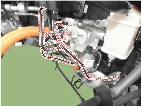
| 13. | Remove the rear brake tube.
|
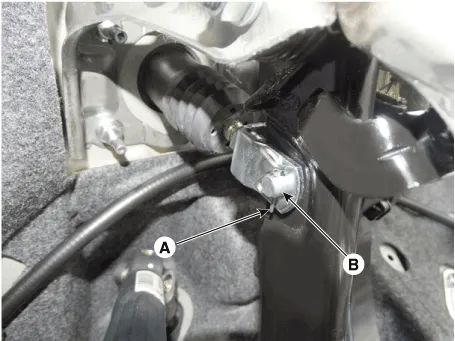
| 14. | Remove the snap pin (A) and clevis pin (B).
|
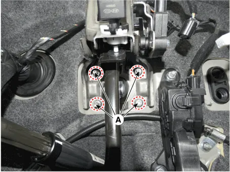
| 15. | Remove the mounting nuts (A) and then remove the brake pedal.
|
| Installation |
| 1. | Installation is the reverse of removal. |
| 2. | Check the brake pedal operation. |
| 3. | After filling the brake fluid in the reservoir, perform the air bleed. (Refer to the AHB System - "AHB System Air Bleeding") |
| 4. | Conduct Brake Pedal Traval sensor(PTS) calibration. (Refer to the Brake System - "Brake Pedal") |
| 5. | Conduct Longitidinal G Sensor Clibration. [HAC/DBC only] |
| 6. | Conduct Pressure sensor Calibration. |
| Diagnostic Procedure Using GDS |
The following section describes how to diagnose faults using a diagnostic instrument.
| 1. | Connect the diagnostic instrument to the self-diagnostic connector (16-pin) beneath the crash pad on the side of driver's seat, and then turn on the ignition to activate the diagnostic instrument. |
| 2. | In the GDS Vehicle Type Selection menu, select "Vehicle Type" and "ABS/ESC" System, and then opt for "OK." [Brake Pedal Sensor Calibration]
[Pressure Sensor Calibration]
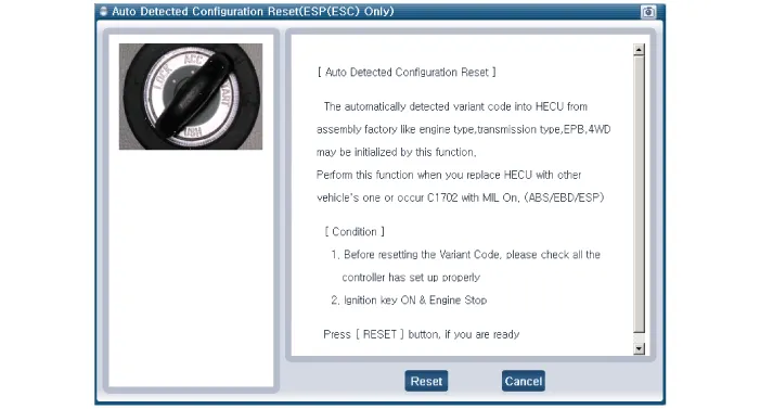
[Auto Detected Configuration Reset]
[Longitidinal G Sensor Clibration]
|
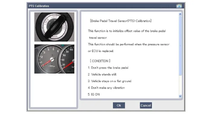
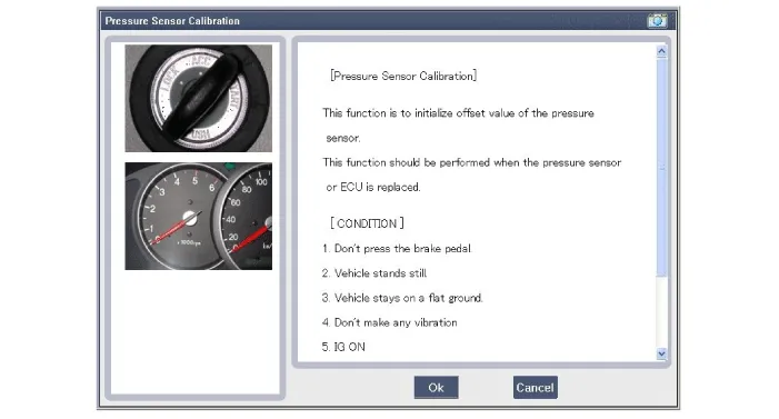
| 3. | Turn ignition switch off and on after calibration procedure. |
| 4. | Confirm success of calibration. |
Components • IBAU (Intergrated Brake Actuation Unit) must not be disassembled.1. Intergrated Brake Actuation Unit (IBAU) ECU2.
Components • PSU (Presser Source Unit) must not be disassembled.1. Pressure Source Unit (PSU)2. Pressure Source Unit (PSU) connector3.
Other information:
Hyundai Ioniq (AE) 2017-2022 Service & Repair Manual: Description and operation
DescriptionThe smart cruise control system allows a driver to program the vehicle to control the speed and following distance by detecting the vehicle ahead without depressing the brake pedal and the accelerator pedal.1.Cruise speed control : The vehicle maintains the selected speed if there are not vehicles ahead.
Hyundai Ioniq (AE) 2017-2022 Service & Repair Manual: Specifications
S
Categories
- Manuals Home
- Hyundai Ioniq Owners Manual
- Hyundai Ioniq Service Manual
- Hybrid Vehicle Engine Compartment
- DCT(Dual Clutch Transmission) System
- Troubleshooting
- New on site
- Most important about car

Copyright © 2026 www.hioniqae.com - 0.0167