Hyundai Ioniq (AE): Inhibitor Switch / Description and operation
| Description |
| • |
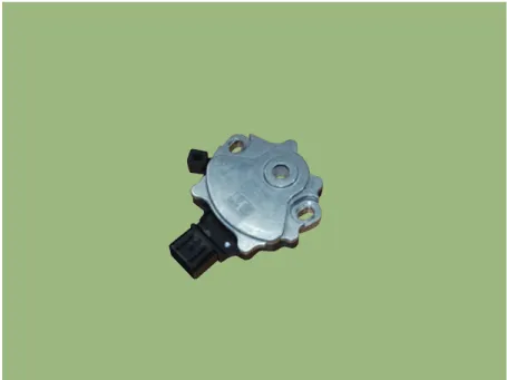
Components location : DCT (Dual Clutch Transmission)
|
| • |
Function
- The inhibitor switch mounted on the upper of transaxle and connected with shifter lever. - The inhibitor switch has four points of contact and it makes the signals(S1, S2, S3, S4). - The inhibitor switch signals delivered at the TCM according to control of the shift lever positions(P, R, N, D) and it is used to control of the gear setting. |
Components1. Inhibitor switch2. Manual control lever
Specificationsâ–· Type: Combination of output signals from 4 terminalsâ–· Specifications Item Specifications Output typeCombination of output signalsPower supply (V)12Signal Code Table PP-RRR-NNN-DDS1(-)(-)00000S20(-)(-)(-)000S3000(-)(-)(-)0S400000(-)(-)
Other information:
Hyundai Ioniq (AE) 2017-2022 Service & Repair Manual: Photo Sensor. Repair procedures
Inspection1.Turn the ignition switch ON.2.Connect the GDS.3.Emit intensive light toward the photo sensor using a lamp, and check the output voltage change.4.The voltage will rise with higher intensive light and reduce with lower intensive light.1. Auto light signal2.
Hyundai Ioniq (AE) 2017-2022 Service & Repair Manual: Description and operation
DescriptionIn ordinary cars, the mechanical water pump mounted on the engine for heating purposes is activated to circulate the cooling water, but in hybrid cars, AEWP is used to circulate the cooling water when the engine is not operating. Classification System Cooling water used
Categories
- Manuals Home
- Hyundai Ioniq Owners Manual
- Hyundai Ioniq Service Manual
- Heating, Ventilation and Air Conditioning
- Engine Mechanical System
- Engine Clutch System
- New on site
- Most important about car
