Hyundai Ioniq (AE): Driveshaft Assembly / Front Driveshaft. Repair procedures
| Removal |
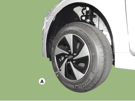
| 1. | Loosen the wheel nuts slightly. Raise the vehicle, and make sure it is securely supported. |
| 2. | Remove the front wheel and tire (A) from the front hub.
|

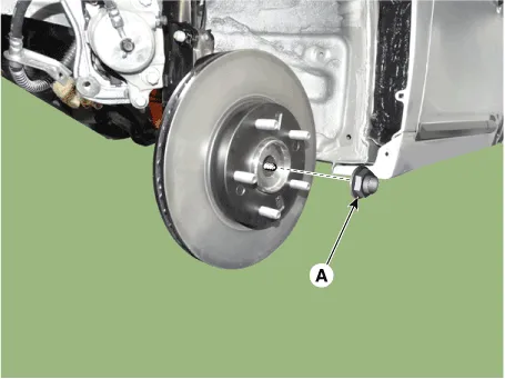
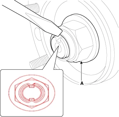
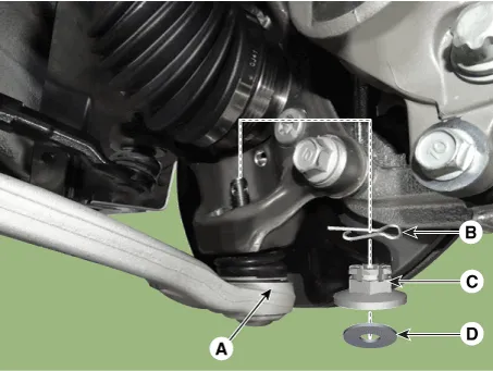
| 3. | Loosen the driveshaft caulking nut (A).
|
| 4. | Remove the tie rod end ball joint.
|
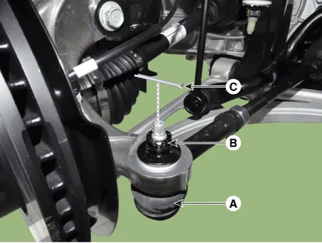
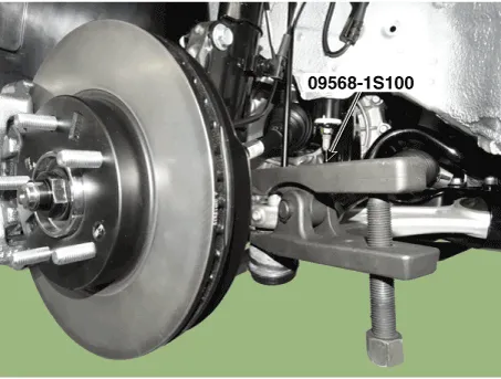
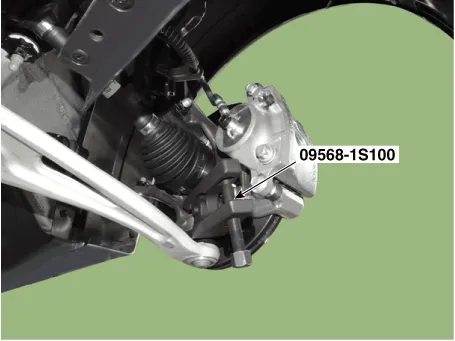
| 5. | Loosen the lower arm nut and then remove the lower arm ball joint by using SST(09568-1S100).
|
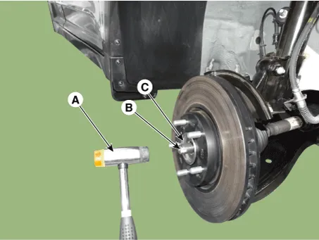
| 6. | Using a plastic hammer (A), remove the front driveshaft (B) from the knuckle assembly (C).
|
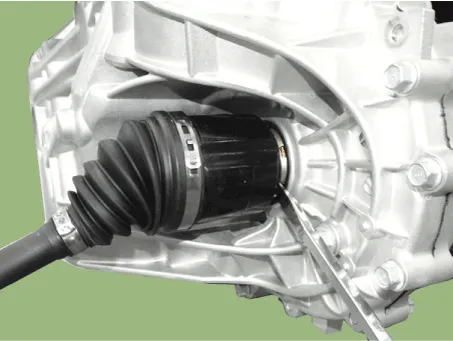
| 7. | Loosen the inner shaft mounting bolts and then remove the driveshaft RH.
|
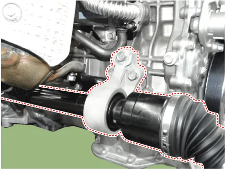
| 8. | Insert a pry bar between the transaxle case and joint case, and separate the driveshaft.
|
| 9. | Install in the reverse order of removal. |
| 10. | Check the front alignment. (Refer to Suspension System - "Front Alignment") |
Components1. Driveshaft (LH)2. Inner shaft bearing bracket3. Driveshaft (RH)
Components1. BJ assembly 2. Circlip 3. BJ boot band 4. BJ boot 5. Shaft6. TJ boot band7. TJ boot8. Spider assembly9. Snap ring10. TJ Housing11. Circlip
Other information:
Hyundai Ioniq (AE) 2017-2022 Service & Repair Manual: Evaporator Temperature Sensor. Repair procedures
Inspection1.Turn the ignition switch OFF.2.Disconnect the evaporator temperature sensor connector.3.Measure the resistance between terminal "+" and "-" of the evaporator temperature sensor.Specification Evaporator core temperature [°C (°F)] Resistance [KΩ]
Hyundai Ioniq (AE) 2017-2022 Service & Repair Manual: Blower Unit. Components and components location
Component Location1. Blower unit assembly Components1. Duct Seal2. Intake duct case3. Air intake door assembly4. Intake door5. Seal6. Intake duct case (A)7. Air filter cover (A)8. Intake actuator9. Air filter cover10. Air filter 11. Blower unit pad12.
Categories
- Manuals Home
- Hyundai Ioniq Owners Manual
- Hyundai Ioniq Service Manual
- Engine Control/Fuel System
- Theft-alarm System
- If the 12 Volt Battery is Discharged (Hybrid Vehicle)
- New on site
- Most important about car
