
Hyundai Ioniq (AE): Convenient features of your vehicle / Instrument Cluster

■Hybrid vehicle • Type A
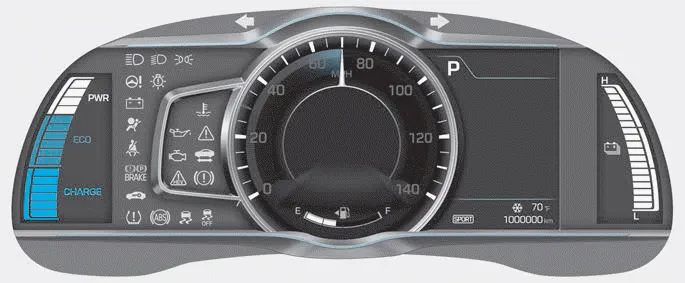
■Hybrid vehicle • Type B
1. Power gauge
2. Speedometer
3. Battery SOC (State of Charge) gauge
4. Fuel gauge
5.Warning and indicator lights
6. LCD display (including Trip computer)
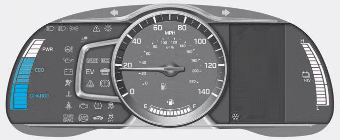
■Plug-in hybrid vehicle • Type A
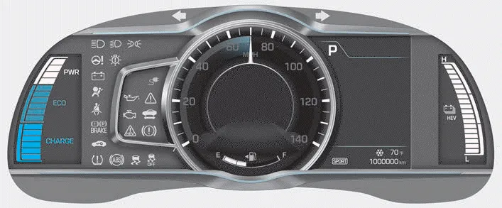
■Plug-in hybrid vehicle • Type B
1. Power gauge
2. Speedometer
3. Battery SOC (State of Charge) gauge
4. Fuel gauge
5.Warning and indicator lights
6. LCD display (including Trip computer)
1. To install the fuel tank cap, turn it clockwise until it "clicks" one time. 2. Close the fuel filler door until it is latched securely. WARNING Gasoline is highly flammable and explosive.
Instrument panel illumination When the vehicle's position lights or headlights are on, press the illumination control button to adjust the brightness of the instrument panel illumination.
Other information:
Hyundai Ioniq (AE) 2017-2022 Service & Repair Manual: emperature Control Actuator. Description and operation
DescriptionThe temperature control actuator is located at the heater unit. It regulates the temperature by the procedure as follows. The signal from the control unit adjusts the position of the temperature door by operating the temperature switch. Then the temperature will be regulated by the hot/cold air ratio decided by the position of the temper
Hyundai Ioniq (AE) 2017-2022 Service & Repair Manual: Front Radar Unit. Repair procedures
Removal1.Remove the front bumper.(Refer to Body - "Front Bumper")2.Disconnect the smart cruise control unit connector (A).3.Remove the smart cruise control nuit assembly (B) from thevehicle after loosening mounting bolts.Installation1.Install in the reverse order of removal.
Categories
- Manuals Home
- Hyundai Ioniq Owners Manual
- Hyundai Ioniq Service Manual
- Repair procedures
- Engine Clutch System
- Engine Mechanical System
- New on site
- Most important about car
