Hyundai Ioniq (AE): Low Voltage DC/DC Converter (LDC) / Repair procedures
| Removal |
|

| 1. | Shut off the high voltage circuit. (Refer to Hybrid Control System - "High Voltage Shutoff Procedure") |
| 2. | Remove the air cleaner assembly and air duct. (Refer to Engine Mechanical System - "Air Cleaner") |
| 3. | Remove the ECM & TCM bracket assembly. (Refer to Engine Control/Fuel System - "Engine Control Module") |
| 4. | Drain the coolant of hybrid motor cooling system. (Refer to Hybrid Motor Cooling System - "Coolant") |
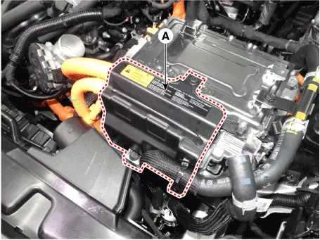
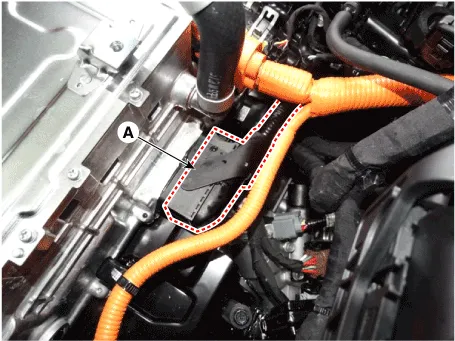
| 5. | Remove the HPCU protector (A) after loosening the mounting bolts.
|
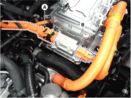
| 6. | Disconnect the motor power cable connector (A) and HSG power cable conector (B).
|
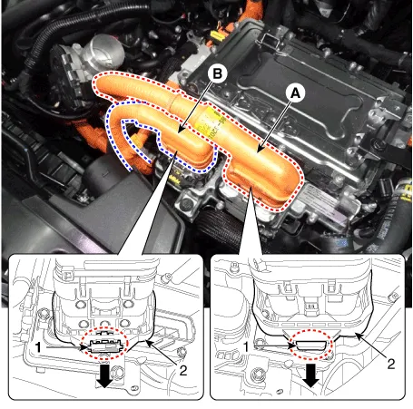
| 7. | Disconnect the power cable (A) [↔ High voltage battery system assembly] and power cable (B) [↔ HSG & Electric A/C compressor].
|

| 8. | Disconnect the HCU & inverter (MCU) connector (A).
|
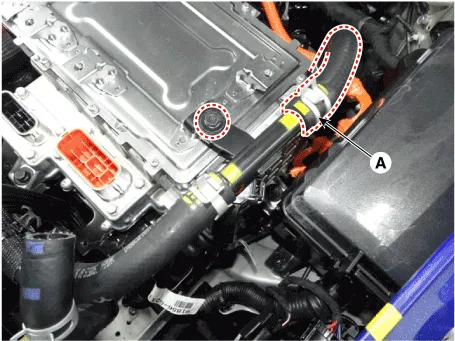
| 9. | Disconnect the coolant outlet hose & pipe (A) after loosening the mounting bolt.
|
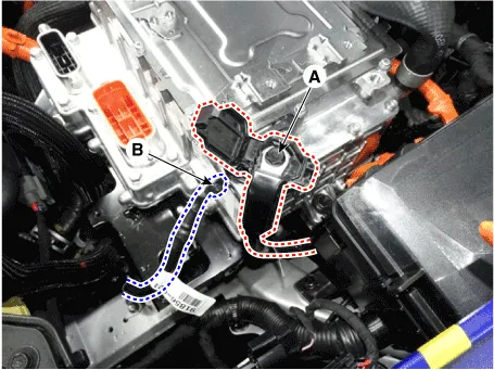
| 10. | Disconnect the LDC power output cable (A) and LDC ground (-) cable (C) after loosening the mounting bolt and nut.
|
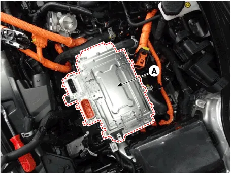
| 11. | Remove the HPCU (A) after loosening the mounting bolts.
|
| Installation |
|
| 1. | Install the LDC in the reverse order of removal.
|
| 2. | Refill the hybrid motor cooling system coolant and perform air bleeding by using the GDS. (refer to Hybrid Motor Cooling System - "Coolant")
|

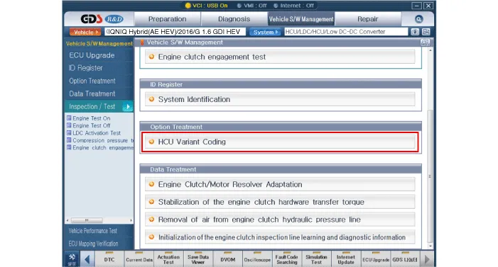
HCU Variant Coding
| 1. | Turn the ignition switch OFF. |
| 2. | Connect the KDS / GDS to Data Link Connector (DLC). Turn the ignition switch ON. |
| 3. | Select "Vehicle, Model year, Engine, System". |
| 4. | Select "Vehicle S/W Management". |
| 5. | Select "HCU Variant Coding".
|
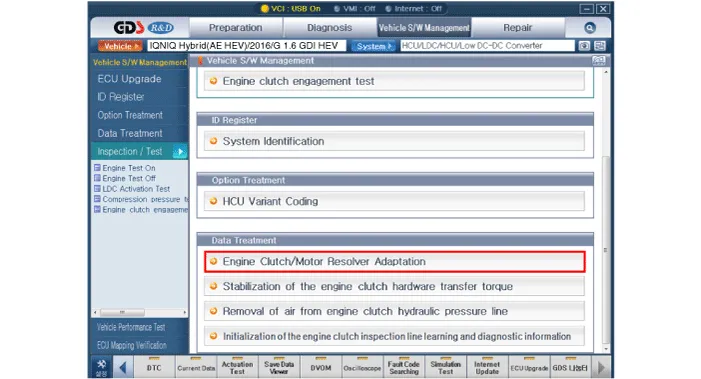
Engine clutch/motor resolver adaptation
| 1. | Turn the ignition switch OFF. |
| 2. | Connect the KDS / GDS to Data Link Connector (DLC). Turn the ignition switch ON. |
| 3. | Select "Vehicle, Model year, Engine, System". |
| 4. | Select "Vehicle S/W Management". |
| 5. | Select "Engine clutch/motor resolver adaptation.".
|
Schematic Diagram
Other information:
Hyundai Ioniq (AE) 2017-2022 Service & Repair Manual: Description and operation
DescriptionIn ordinary cars, the mechanical water pump mounted on the engine for heating purposes is activated to circulate the cooling water, but in hybrid cars, AEWP is used to circulate the cooling water when the engine is not operating. Classification System Cooling water used
Hyundai Ioniq (AE) 2017-2022 Service & Repair Manual: Components and components location
C
Categories
- Manuals Home
- Hyundai Ioniq Owners Manual
- Hyundai Ioniq Service Manual
- Body (Interior and Exterior)
- Repair procedures
- Hybrid Vehicle Engine Compartment
- New on site
- Most important about car

Copyright © 2026 www.hioniqae.com - 0.0184