Hyundai Ioniq (AE): Rear Axle Assembly. Rear Hub - Carrier / Repair procedures
| Removal |
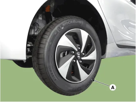
| 1. | Loosen the wheel nuts slightly. Raise the vehicle, and make sure it is securely supported. |
| 2. | Remove the rear wheel and tire (A) from the rear hub.
|

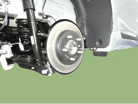
| 3. | Remove the rear brake caliper. (Refer to Brake System - "Rear Disc Brake") |
| 4. | Loosen the screws and then remove the brake disc.
|
| 5. | Disconnect the rear wheel speed sensor connector (A).
|
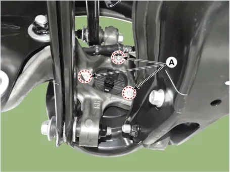
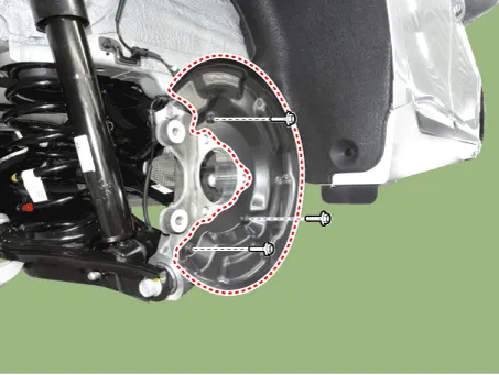
| 6. | Loosen the mounting bolts (A) and then remove the hub bearing.
|
| 7. | Loosen the bolts and then remova the dust cover.
|
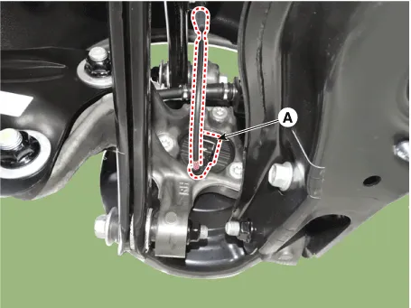
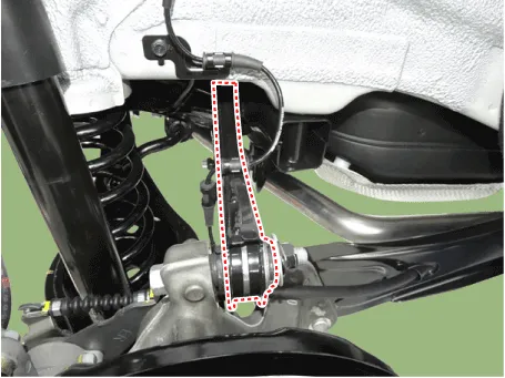
| 8. | Loosen the rear upper arm mounting bolt and then remove the rear upper arm (A).
|
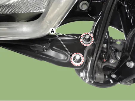
| 9. | Loosen the trailing arm mounting nuts (A), and then remove the trailing arm.
|
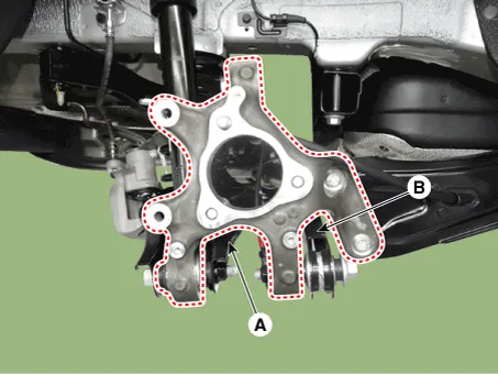
| 10. | Loosen the bolt and nut and then remove the lower arm (A), assist arm (B).
|
| 11. | Install in the reverse order of removal. |
| 12. | Check the wheel Alignment. (Refer to Tires/Wheels - "Alignment") |
| Inspection |
| 1. | Check the hub for cracks and the splines for wear. |
| 2. | Check the brake disc for scoring and damage. |
| 3. | Check the rear axle carrier for cracks. |
| 4. | Check the bearing for cracks or damage. |
| 5. | Replace only the sensor cap when the warning light turns on due to a defective sensor cap of the hub bearing. (Refer to Brake System - "Rear Wheel Speed Sensor") |
Components1. Rear axle2. Dust cover3. Rear hub bearing4. Rear brake disc
Other information:
Hyundai Ioniq (AE) 2017-2022 Service & Repair Manual: Mode Control Actuator. Components and components location
C
Hyundai Ioniq (AE) 2017-2022 Service & Repair Manual: Blower Unit. Components and components location
Component Location1. Blower unit assembly Components1. Duct Seal2. Intake duct case3. Air intake door assembly4. Intake door5. Seal6. Intake duct case (A)7. Air filter cover (A)8. Intake actuator9. Air filter cover10. Air filter 11. Blower unit pad12.
Categories
- Manuals Home
- Hyundai Ioniq Owners Manual
- Hyundai Ioniq Service Manual
- General Information
- If the 12 Volt Battery is Discharged (Hybrid Vehicle)
- Jump starting procedure
- New on site
- Most important about car

Copyright © 2026 www.hioniqae.com - 0.0174