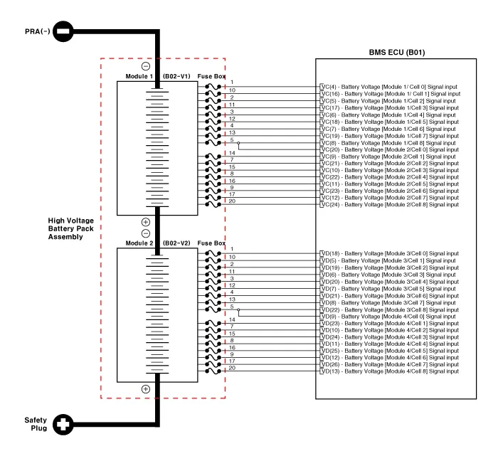
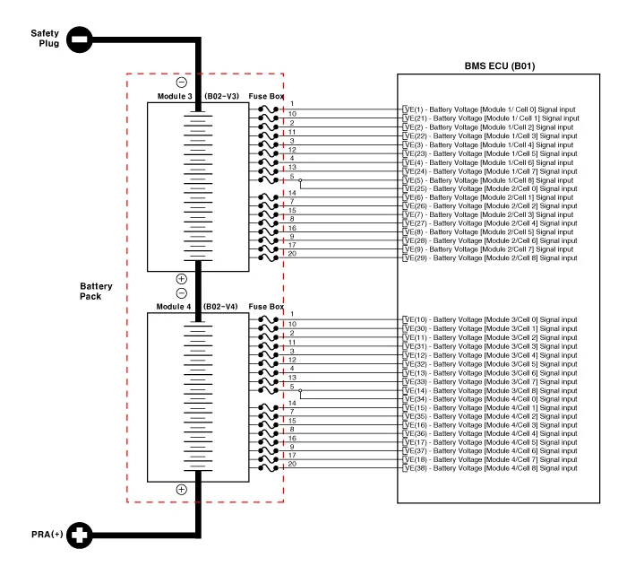
Hyundai Ioniq (AE): Battery Fuse Box / Schematic diagrams
| Circuit Diagram |
Trouble Symptom Charts– Follow the guide in case of DTC.
Removal • Be sure to read and follow the "General Safety Information and Caution" before doing any work related with the high voltage system.
Other information:
Hyundai Ioniq (AE) 2017-2022 Service & Repair Manual: Front View Camera Unit. Repair procedures
Removal1.Disconnect the negative (-) battery terminal.2.Remove the front view camera cover (A).3.Disconnect the front view camera connector (A).4.Remove the front view camera after disengaging the mounting bracket (A).Installation1.Align front view camera with windshield bracket using forward edge point (A).
Hyundai Ioniq (AE) 2017-2022 Service & Repair Manual: Smart Cruise Control (SCC) Switch. Repair procedures
Removal1.Disconnect the negative (-) battery terminal.2.Remove the steering wheel assembly.(Refer to Steering System -"Steering Wheel")3.Remove the steering back cover (A).4.Remove the steering remote control connector (A).5.Remove the steering remote control (A), after loosening the screws.
Categories
- Manuals Home
- Hyundai Ioniq Owners Manual
- Hyundai Ioniq Service Manual
- Repair procedures
- DCT(Dual Clutch Transmission) System
- Theft-alarm System
- New on site
- Most important about car
