Hyundai Ioniq (AE): High Voltage Battery Control System / Battery Current Sensor. Repair procedures
| Removal |
|

|

| Installation |
|
|
| Inspection |
|
| 1. | Connect the GDS to the Data Link Connector (DLC). |
| 2. | Turn the ignition switch ON. |
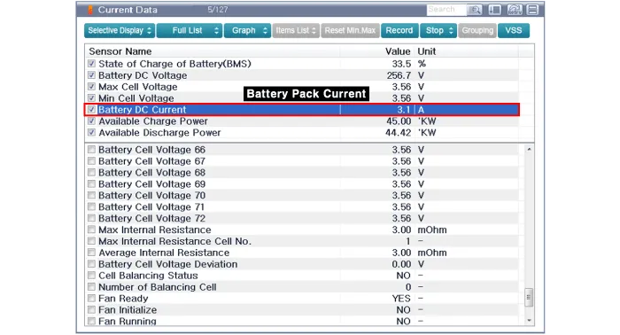
| 3. | Check the battery current in GDS service data.
|
Circuit Diagram
DescriptionThe main fuse is mounted in the safety plug and protects the high voltage battery and high voltage circuits from overcurrent.
Other information:
Hyundai Ioniq (AE) 2017-2022 Service & Repair Manual: Ambient Temperature Sensor. Description and operation
DescriptionThe ambient temperature sensor is located at the front of the condenser and detects ambient air temperature. It is a negative type thermistor; resistance will increase with lower temperature, and decrease with higher temperature.The sensor output will be used for discharge temperature control, temperature regulation door contrl, blower m
Hyundai Ioniq (AE) 2017-2022 Service & Repair Manual: Rear Corner Safety ON/OFF Switch. Repair procedures
Inspection1.Disconnect the negative (-) battery terminal.2.Remove the crash pad lower panel.(Refer to Body - "Crash Pad Lower Panel")3.Remove the lower crash pad switch assembly (A) after disengaging the mounting clip.4.Remove the rheostat switch connector (A).
Categories
- Manuals Home
- Hyundai Ioniq Owners Manual
- Hyundai Ioniq Service Manual
- Checking the Coolant Level
- Maintenance
- Engine Mechanical System
- New on site
- Most important about car
