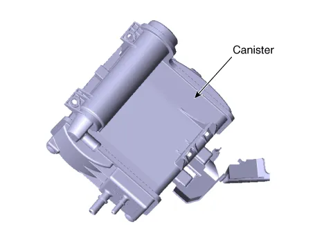
Hyundai Ioniq (AE): Evaporative Emission Control System / Canister. Repair procedures
| Removal |
| 1. | Turn ignition switch OFF and disconnect the negative (-) battery cable. |
| 2. | Remove the fuel tank. (Refer to Engine Control/Fuel System - "Fuel Tank") |
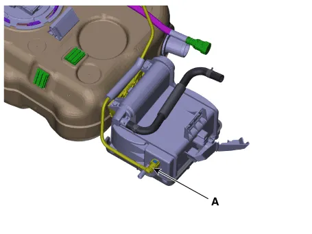
| 3. | Disconnect the vapor tube quick-connector (A).
|
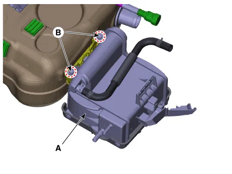
| 4. | Remove the canister (A) from the fuel tank after loosening the bolts (B).
|
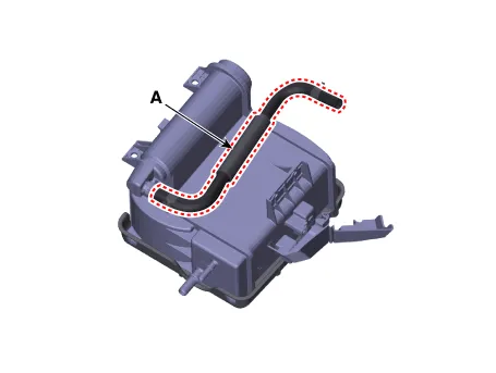
| 5. | Disconnect the vapor hose (A).
|
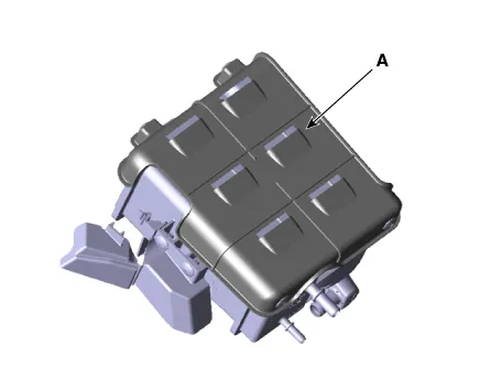
| 6. | Remove the canister protectors (A).
|
| Inspection |
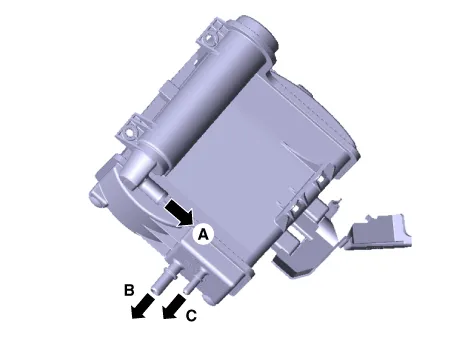
| 1. | Check for the following items visually.
A : Canister ↔ Atmosphere B : Canister ↔ Intake Manifold C : Canister ↔ Fuel Tank |
| Installation |
| 1. | Install in the reverse order of removal. |
Schematic DiagramCanisterCanister is filled with charcoal and absorbs evaporated vapor in fuel tank. The gathered fuel vapor in canister is drawn into the intake manifold by the ECM/PCM when appropriate conditions are set.
Replacement1.Turn ignition switch OFF and disconnect the negative (-) battery cable.2.Remove the filler-neck assembly(Refer to Engine Control/Fuel System - "Filler-Neck Assembly")3.
Other information:
Hyundai Ioniq (AE) 2017-2022 Service & Repair Manual: Duct Sensor. Repair procedures
Inspection1.Check that the voltage values of No. 1, 2 duct sensors change1. Sensor (+ 5V)2. Sensor groundSpecification Ambient temperature [°C (°F)] Resistance (kΩ) Voltage (V) 50 (122)1.
Hyundai Ioniq (AE) 2017-2022 Service & Repair Manual: Special service tools
Special Service Tools Tool Name / Number Illustration Description LKA Compensator(09964-C1100)Used for compensating front view camera unitBCW Sensor Correction Tool Set(09958-3T500)Used to correct the blind-spot radar unit.
Categories
- Manuals Home
- Hyundai Ioniq Owners Manual
- Hyundai Ioniq Service Manual
- General Information
- If the 12 Volt Battery is Discharged (Hybrid Vehicle)
- Brake System
- New on site
- Most important about car
