Hyundai Ioniq (AE): Cylinder Head Assembly / Cylinder Head. Components and components location
Hyundai Ioniq (AE) 2017-2022 Service & Repair Manual / Engine Mechanical System / Cylinder Head Assembly / Cylinder Head. Components and components location
| Components |
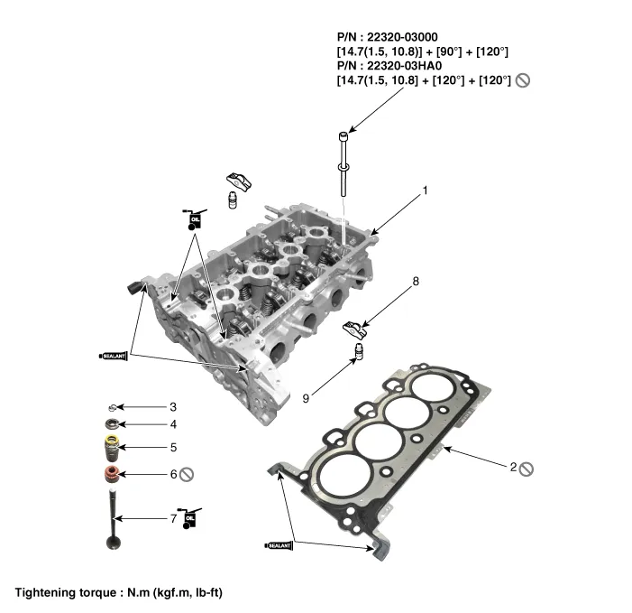
| 1. Cylinder head assembly 2. Cylinder head gasket 3. Retainer lock 4. Retainer 5. Valve spring | 6. Valve stem seal 7. Valve 8. Swing arm 9. Hydraulic lash adjuster (HLA) |
Removal • Be sure to read and follow the “General Safety Information and Caution” before doing any work related with the high voltage system.
RemovalEngine removal is not required for this procedure. • Be sure to read and follow the "General Safety Information and Caution" before doing any work related with the high voltage system.
Other information:
Hyundai Ioniq (AE) 2017-2022 Service & Repair Manual: Repair procedures
Self Diagnosis1.Self-diagnosis process. • When operating the self-diagnostics, the below fault (self-diagnostics code) will blink at 0.5 seconds interval on the temperature display settings (driver's side only) and the remaining symbols are OFF .
Hyundai Ioniq (AE) 2017-2022 Service & Repair Manual: Cruise Control Switch. Components and components location
C
Categories
- Manuals Home
- Hyundai Ioniq Owners Manual
- Hyundai Ioniq Service Manual
- Troubleshooting
- If the 12 Volt Battery is Discharged (Hybrid Vehicle)
- Transmission Gear Oil. Repair procedures
- New on site
- Most important about car

Copyright © 2026 www.hioniqae.com - 0.0167