Hyundai Ioniq (AE): Dual Clutch System / Dual Clutch Assembly. Repair procedures
| Removal |
| 1. | Remove the dual clutch transmission from the vehicle. (Refer to Dual Clutch Transmission System - "Dual Clutch Transmission") |
| 2. | Remove the hybrid motor assembly from the dual clutch transmission assembly. (Refer to Hybrid Motor System - "Hybrid Motor Assembly") |
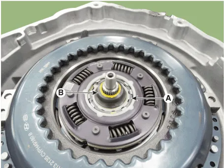
| 3. | Remove the retaining (A) and then removing the spline hub (B).
|
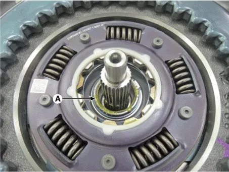
| 4. | Remove the snap ring (A).
|
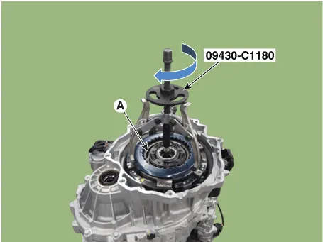
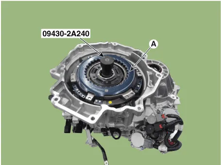
| 5. | Remove the dual clutch assembly (A) by using the special service tool [SST No.: 09430-C1180].
|
| Installation |
|

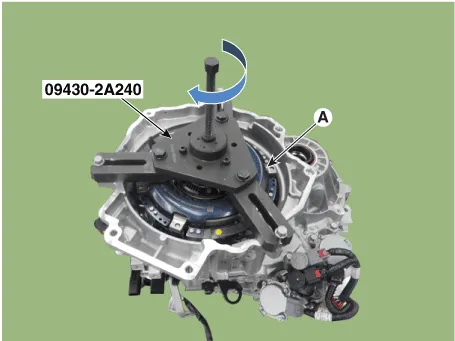
| 1. | Install the SST (No.:09430-2A240) on the support bearing with in the dual clutch assembly (A).
|
| 2. | Install the special service tool (09430-2A240) on the clutch housing side. Then, install the dual clutch assembly (A) by rotating the shaft of service tool.
|
| 3. | Install the snap ring (A).
|

| 4. | Install the spline hub (B) and the install the retaining ring (A).
|
| 5. | Install the hybrid motor assembly in the dual clutch transmission assembly. (Refer to Hybrid Motor System - "Hybrid Motor Assembly") |
| 6. | Install the dual clutch transmission to vehicle. (Refer to Dual Clutch Transmission System - "Dual Clutch Transmission") |
| 7. | Perform the work procedures for abrasion compensation reset after installing the new dual clutch assembly. (Refer to Clutch Actuator Assembly - "Adjustment") |
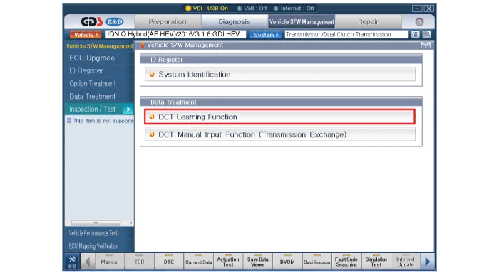
| 8. | Perform the clutch touch point learning procedure using the GDS after replacing the dual clutch assembly.
|
Components1. Retaining ring2. Spline hub3. Snap ring4. Dual clutch assembly
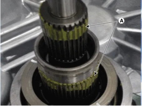
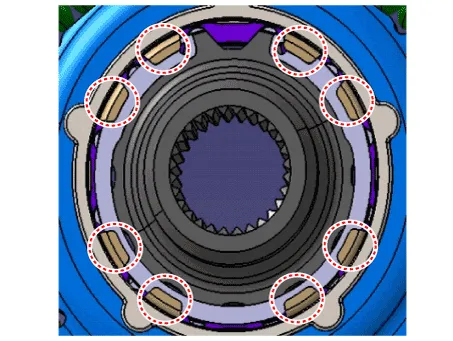
Components1. Clutch housing2. Engagement bearing 2 (Even)3. Engagement bearing 1 (Odd)4. Engagement bearing sleeve5. Engagement frok 1 (Odd)6. Engagement frok 2 (Even)
Other information:
Hyundai Ioniq (AE) 2017-2022 Service & Repair Manual: Photo Sensor. Description and operation
Description The photo sensor is located at the center of the defrost nozzles.The photo sensor contains a photovoltaic (sensitive to sunlight) diode. The solar radiation received by its light receiving portion, generates an electromotive force in proportion to the amount of radiation received which is transferred to the automatic temperature control
Hyundai Ioniq (AE) 2017-2022 Service & Repair Manual: Auto Defogging Sensor. Description and operation
DescriptionThe auto defogging sensor is installed on the front window glass. The sensor judges and sends signal if moisture occurs to blow out wind for defogging. The air conditioner control module receives signal from the sensor and restrains moisture and eliminate defog by controlling the intake actuator, A/C, auto defogging actuator, blower moto
Categories
- Manuals Home
- Hyundai Ioniq Owners Manual
- Hyundai Ioniq Service Manual
- Jump Starting
- Front Disc Brake. Repair procedures
- Body (Interior and Exterior)
- New on site
- Most important about car
