Hyundai Ioniq (AE): Driveshaft Assembly / Front Driveshaft. Repair procedures
| Removal |
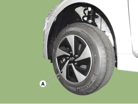
| 1. | Loosen the wheel nuts slightly. Raise the vehicle, and make sure it is securely supported. |
| 2. | Remove the front wheel and tire (A) from the front hub.
|

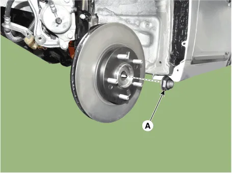
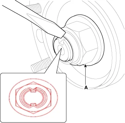
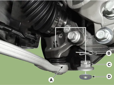
| 3. | Loosen the driveshaft caulking nut (A).
|
| 4. | Remove the tie rod end ball joint.
|
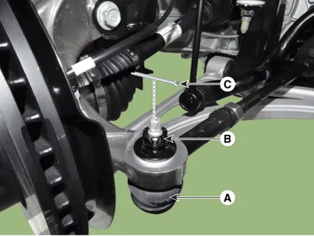
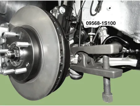
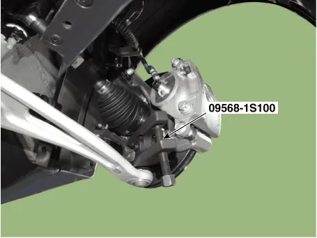
| 5. | Loosen the lower arm nut and then remove the lower arm ball joint by using SST(09568-1S100).
|
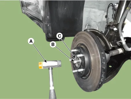
| 6. | Using a plastic hammer (A), remove the front driveshaft (B) from the knuckle assembly (C).
|
| 7. | Loosen the inner shaft mounting bolts and then remove the driveshaft RH.
|
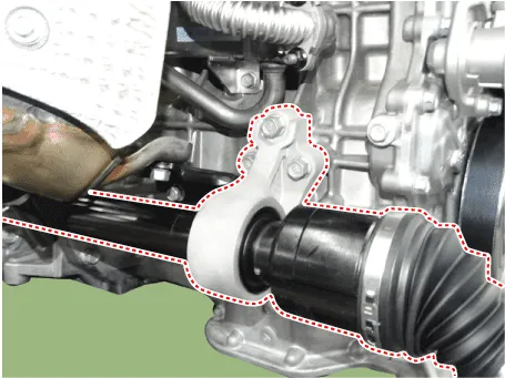
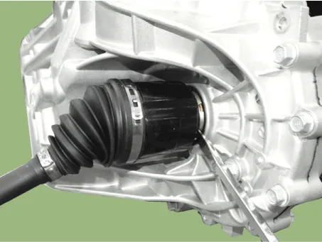
| 8. | Insert a pry bar between the transaxle case and joint case, and separate the driveshaft.
|
| 9. | Install in the reverse order of removal. |
| 10. | Check the front alignment. (Refer to Suspension System - "Front Alignment") |
Components1. Driveshaft (LH)2. Inner shaft bearing bracket3. Driveshaft (RH)
Components1. BJ assembly 2. Circlip 3. BJ boot band 4. BJ boot 5. Shaft6. TJ boot band7. TJ boot8. Spider assembly9. Snap ring10. TJ Housing11. Circlip
Other information:
Hyundai Ioniq (AE) 2017-2022 Service & Repair Manual: Auto Defogging Sensor. Repair procedures
Diagnosis With GDS1.The heating, ventilation and air conditioning can be quickly diagnosed failed parts with vehicle diagnostic system (GDS).※ The diagnostic system (GDS) provides the following information.(1) Self diagnosis : Checking the failure code (DTC) and display.
Hyundai Ioniq (AE) 2017-2022 Service & Repair Manual: Front Radar Unit. Description and operation
DescriptionThe smart cruise control unit is installed on the front right side of the chassis. A radar sensor is embedded in the front section of the unit. This sensor detects vehicles and objects in front of the vehicle. The radar sensor can detect up to 64 objects ahead of a vehicle.
Categories
- Manuals Home
- Hyundai Ioniq Owners Manual
- Hyundai Ioniq Service Manual
- Transmission Gear Oil. Repair procedures
- Body (Interior and Exterior)
- Repair procedures
- New on site
- Most important about car
