Hyundai Ioniq: Hybrid Control System / HCU (Hybrid Control Unit). Repair procedures
| •
| Be sure to read and follow the "General Safety Information and Caution" before doing any work related with the high voltage system. Failure to follow the safety instructions may result in serious electrical injuries. |
|
| 1. | Refer to "HPCU". | •
| The HCU is integrated into the HPCU that can’t be disassembled. So refer to "HPCU" for the removal or installation procedure of the HCU. |
|
|
| 2. | Perform the clutch pressure sensor calibration. (Refer to "Clutch Pressure Sensor") |
HCU Terminal and Input / Output SignalTerminal FunctionConnector [C133-S]
Pin No
Description
Connected to
1HCU GroundChassis ground2HCU GroundChassis ground3HCU GroundChassis ground4Battery power (B+)Battery5Battery power (B+)Battery6Battery power (B+)Battery7- 8- 9- 10- 11- 12- 13- 14- 15Brake Switch 2 signal inputBrake Switch (NC, IG1)16Brake Switch 1 signal inputBrake Switch (NO, B+)17- 18- 19- 20- 21- 22- 23- 24- 25- 26- 27- 28- 29- 30- 31-32-33-34- 35- 36- 37- 38Start signal inputSmart Key Unit39- 40- 41- 42- 43- 44- 45- 46- 47- 48- 49- 50- 51- 52- 53- 54- 55- 56- 57- 58- 59- 60- 61- 62- 63- 64- 65- 66- 67- 68- 69- 70- 71- 72- 73IGN signal inputSmart Key Unit74- 75- 76- 77- 78Powertrain CAN [High] signal inputOther control modules79Powertrain CAN [Low] signal inputOther control modules80- 81Hybrid CAN [High] signal inputOther control modules82Hybrid CAN [Low] signal inputOther control modules83- 84- 85- 86- 87- 88- 89- 90- 91- 92- 93- 94- Input/Output signalConnector [C133-S]
Pin no
Description
Condition
Type
Level
1HCU GroundAlwaysDC VoltageMax...
DescriptionThe Brake Switch is installed on the brake pedal and linked with the HCU and stop lamp. It sensors the status of the brake pedal (Release, Push) and transmits the signal to the HCU...
Other information:
DescriptionIf the Gasoline Engine Control system components (sensors, ECM, injector, etc.) fail, interruption to the fuel supply or failure to supply the proper amount of fuel for various engine operating conditions will result. The following situations may be encountered...
Removal1.Disconnect the negative (-) battery terminal.2.Remove the steering wheel assembly.(Refer to Steering System - "Steering Wheel")3.Remove the steering back cover (A).4.Remove the steering remote control connector (A).5.Remove the steering remote control after loosening the screws...
Categories
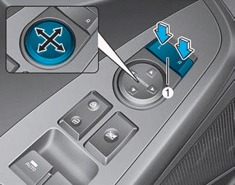
Adjusting the side mirrors:
1. Press either the L (driver's side) or R (passenger's side) button (1) to select
the side view mirror you would like to adjust.
read more


 HCU (Hybrid Control Unit). Schematic diagrams
 Brake Switch. Description and operation