Hyundai Ioniq (AE): Hybrid Control System / HCU (Hybrid Control Unit). Schematic diagrams
Hyundai Ioniq (AE) 2017-2022 Service & Repair Manual / Hybrid Control System / Hybrid Control System / HCU (Hybrid Control Unit). Schematic diagrams
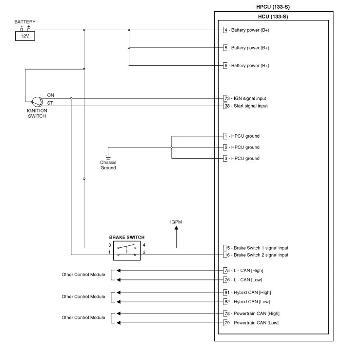
| HCU Terminal and Input / Output Signal |

| Terminal Function |
Connector [C133-S]
|
Pin No
|
Description
|
Connected to
|
| 1 | HCU Ground | Chassis ground |
| 2 | HCU Ground | Chassis ground |
| 3 | HCU Ground | Chassis ground |
| 4 | Battery power (B+) | Battery |
| 5 | Battery power (B+) | Battery |
| 6 | Battery power (B+) | Battery |
| 7 | - |   |
| 8 | - |   |
| 9 | - |   |
| 10 | - |   |
| 11 | - |   |
| 12 | - |   |
| 13 | - |   |
| 14 | - |   |
| 15 | Brake Switch 2 signal input | Brake Switch (NC, IG1) |
| 16 | Brake Switch 1 signal input | Brake Switch (NO, B+) |
| 17 | - |   |
| 18 | - |   |
| 19 | - |   |
| 20 | - |   |
| 21 | - |   |
| 22 | - |   |
| 23 | - |   |
| 24 | - |   |
| 25 | - |   |
| 26 | - |   |
| 27 | - |   |
| 28 | - |   |
| 29 | - |   |
| 30 | - |   |
| 31 | - | |
| 32 | - | |
| 33 | - | |
| 34 | - |   |
| 35 | - |   |
| 36 | - |   |
| 37 | - |   |
| 38 | Start signal input | Smart Key Unit |
| 39 | - |   |
| 40 | - |   |
| 41 | - |   |
| 42 | - |   |
| 43 | - |   |
| 44 | - |   |
| 45 | - |   |
| 46 | - |   |
| 47 | - |   |
| 48 | - |   |
| 49 | - |   |
| 50 | - |   |
| 51 | - |   |
| 52 | - |   |
| 53 | - |   |
| 54 | - |   |
| 55 | - |   |
| 56 | - |   |
| 57 | - |   |
| 58 | - |   |
| 59 | - |   |
| 60 | - |   |
| 61 | - |   |
| 62 | - |   |
| 63 | - |   |
| 64 | - |   |
| 65 | - |   |
| 66 | - |   |
| 67 | - |   |
| 68 | - |   |
| 69 | - |   |
| 70 | - |   |
| 71 | - |   |
| 72 | - |   |
| 73 | IGN signal input | Smart Key Unit |
| 74 | - |   |
| 75 | - |   |
| 76 | - |   |
| 77 | - |   |
| 78 | Powertrain CAN [High] signal input | Other control modules |
| 79 | Powertrain CAN [Low] signal input | Other control modules |
| 80 | - |   |
| 81 | Hybrid CAN [High] signal input | Other control modules |
| 82 | Hybrid CAN [Low] signal input | Other control modules |
| 83 | - |   |
| 84 | - |   |
| 85 | - |   |
| 86 | - |   |
| 87 | - |   |
| 88 | - |   |
| 89 | - |   |
| 90 | - |   |
| 91 | - |   |
| 92 | - |   |
| 93 | - |   |
| 94 | - |   |
| Input/Output signal |
Connector [C133-S]
|
Pin no
|
Description
|
Condition
|
Type
|
Level
|
| 1 | HCU Ground | Always | DC Voltage | Max. 50 mV |
| 2 | HCU Ground | Always | DC Voltage | Max. 50 mV |
| 3 | HCU Ground | Always | DC Voltage | Max. 50 mV |
| 4 | Battery power (B+) | Always | DC Voltage | Battery Voltage |
| 5 | Battery power (B+) | Always | DC Voltage | Battery Voltage |
| 6 | Battery power (B+) | Always | DC Voltage | Battery Voltage |
| 7 | - |   |   |   |
| 8 | - |   |   |   |
| 9 | - |   |   |   |
| 10 | - |   |   |   |
| 11 | - |   |   |   |
| 12 | - |   |   |   |
| 13 | - |   |   |   |
| 14 | - |   |   |   |
| 15 | Brake Switch 2 signal input | IG ON | DC Voltage | Battery Voltage |
| 16 | Brake Switch 1 signal input | Always | DC Voltage | Battery Voltage |
| 17 | - |   |   |   |
| 18 | - |   |   |   |
| 19 | - |   |   |   |
| 20 | - |   |   |   |
| 21 | - |   |   |   |
| 22 | - |   |   |   |
| 23 | - |   |   |   |
| 24 | - |   |   |   |
| 25 | - |   |   |   |
| 26 | - |   |   |   |
| 27 | - |   |   |   |
| 28 | - |   |   |   |
| 29 | - |   |   |   |
| 30 | - |   |   |   |
| 31 | - | |||
| 32 | - | |||
| 33 | - | |||
| 34 | - |   |   |   |
| 35 | - |   |   |   |
| 36 | - |   |   |   |
| 37 | - |   |   |   |
| 38 | Start signal input | IG ST | DC Voltage | Battery Voltage |
| 39 | - |   |   |   |
| 40 | - |   |   |   |
| 41 | - |   |   |   |
| 42 | - |   |   |   |
| 43 | - |   |   |   |
| 44 | - |   |   |   |
| 45 | - |   |   |   |
| 46 | - |   |   |   |
| 47 | - |   |   |   |
| 48 | - |   |   |   |
| 49 | - |   |   |   |
| 50 | - |   |   |   |
| 51 | - |   |   |   |
| 52 | - |   |   |   |
| 53 | - |   |   |   |
| 54 | - |   |   |   |
| 55 | - |   |   |   |
| 56 | - |   |   |   |
| 57 | - |   |   |   |
| 58 | - |   |   |   |
| 59 | - |   |   |   |
| 60 | - |   |   |   |
| 61 | - |   |   |   |
| 62 | - |   |   |   |
| 63 | - |   |   |   |
| 64 | - |   |   |   |
| 65 | - |   |   |   |
| 66 | - |   |   |   |
| 67 | - |   |   |   |
| 68 | - |   |   |   |
| 69 | - |   |   |   |
| 70 | - |   |   |   |
| 71 | - |   |   |   |
| 72 | - |   |   |   |
| 73 | IGN Signal input | IG ON | DC Voltage | Battery Voltage |
| 74 | - |   |   |   |
| 75 | - |   |   |   |
| 76 | - |   |   |   |
| 77 | - |   |   |   |
| 78 | Powertrain CAN [High] signal input | IG ON | Pulse | Dominant : 2.75 - 4.5 (3.5)V Receive : 2.0 - 3.0 (2.5)V |
| 79 | Powertrain CAN [Low] signal input | IG ON | Pulse | Receive : 2.0 - 3.0 (2.5)V Dominant : 0.5 - 2.25 (1.5)V |
| 80 | - |   |   |   |
| 81 | Hybrid CAN [High] signal input | IG ON | Pulse | Dominant : 2.75 - 4.5 (3.5)V Receive : 2.0 - 3.0 (2.5)V |
| 82 | Hybrid CAN [Low] signal input | IG ON | Pulse | Receive : 2.0 - 3.0 (2.5)V Dominant : 0.5 - 2.25 (1.5)V |
| 83 | - |   |   |   |
| 84 | - |   |   |   |
| 85 | - |   |   |   |
| 86 | - |   |   |   |
| 87 | - |   |   |   |
| 88 | - |   |   |   |
| 89 | - |   |   |   |
| 90 | - |   |   |   |
| 91 | - |   |   |   |
| 92 | - |   |   |   |
| 93 | - |   |   |   |
| 94 | - |   |   |   |
| Circuit Diagram |
Removal • Be sure to read and follow the "General Safety Information and Caution" before doing any work related with the high voltage system.
Removal • Be sure to read and follow the "General Safety Information and Caution" before doing any work related with the high voltage system.
Other information:
Hyundai Ioniq (AE) 2017-2022 Service & Repair Manual: Specifications
S
Hyundai Ioniq (AE) 2017-2022 Service & Repair Manual: Parking Distance Warning (PDW) ON/OFF Switch. Repair procedures
Removal • Put on gloves to prevent hand injuries. • When removing with a flat-tip screwdriver or remover, wrap protective tape around the tools to prevent damage to components.
Categories
- Manuals Home
- Hyundai Ioniq Owners Manual
- Hyundai Ioniq Service Manual
- Suspension System
- Body (Interior and Exterior)
- Hybrid Control System
- New on site
- Most important about car

Copyright © 2026 www.hioniqae.com - 0.0236