Hyundai Ioniq (AE): Cooling System / Radiator. Components and components location
| Components |
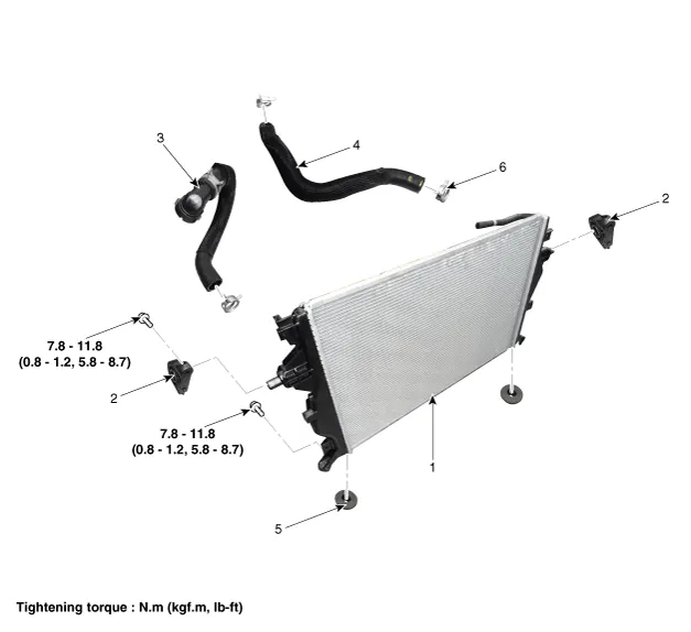
| 1. Radiator assembly 2. Radiator upper mounting bracket 3. Radiator lower hose | 4. Radiator upper hose 5. Mounting insulator 6. Clamp |
Removal and installationCooling Fan Assembly1.Disconnect the battery negative terminal.2.Remove the air cleaner assembly.(Refer to Intake and Exhaust System - "Air Cleaner")3.
Removal and Installation1.Loosen the drain plug, and drain the engine coolant. Remove the reservoir cap to help drain the coolant faster.(Refer to Cooling System - "Coolant")2.
Other information:
Hyundai Ioniq (AE) 2017-2022 Service & Repair Manual: Intake Actuator. Repair procedures
Inspection1.Turn the ignition switch OFF.2.Disconnect the intake actuator connector.3.Verify that the intake actuator operates to the fresh position when connecting 12V to terminal 3 and grounding terminal 4.Verify that the intake actuator operates to the recirculation position when connected in reverse.
Hyundai Ioniq (AE) 2017-2022 Service & Repair Manual: Repair procedures
Removal1.Disconnect the negative (-) battery terminal.2.Remove the tailgate lid trim.(Refer to Body - "TailGate Lid Trim")3.Disconnect the Rear view camera connector (A).4.Remove the Rear view camera assembly after loosening the mounting screws.Installation1.
Categories
- Manuals Home
- Hyundai Ioniq Owners Manual
- Hyundai Ioniq Service Manual
- Jump starting procedure
- Hybrid Control System
- Troubleshooting
- New on site
- Most important about car
