Hyundai Ioniq (AE): Clutch Actuator Assembly / Repair procedures
| 1. | Turn ignition switch OFF and disconnect the battery negative (-) terminal. |
| 2. | Remove the engine room under cover. (Refer to Engine Mechanical System - "Engine Room Under Cover") |
| 3. | Disconnect the clutch actuator connector (A). 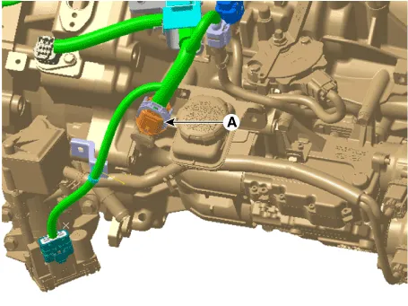
|
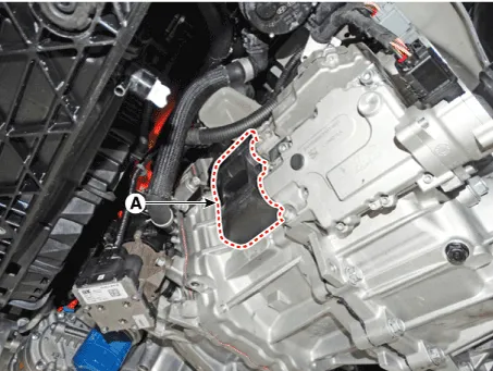
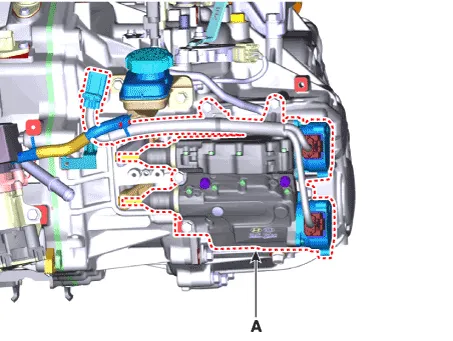
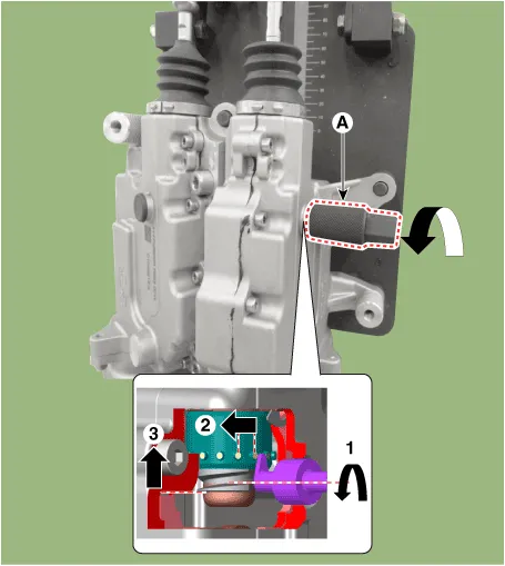
| 4. | Remove the fork cover (A). Tightening torque : 3.9 - 5.9 N.m (0.4 - 0.6kgf.m, 2.9 - 4.3 lb-ft) |
|
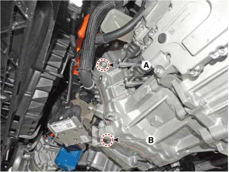
| 5. | Remove the hybrid motor mounting bolts (A, B) Tightening torque : 42.2 - 53.9 N.m (4.3 - 5.5 kgf.m, 31.1 - 39.8 lb-ft) |
|
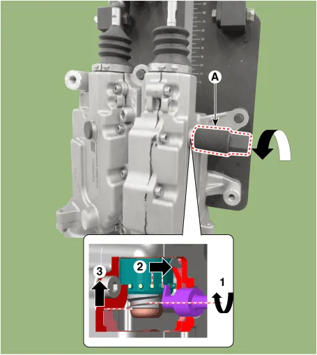
| 6. | Fix the clutch engagement fork after installing special service tool (09430-G2100). 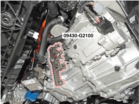
|
| 7. | Remove the clutch actuator (A). Tightening torque : 19.6 - 26.5 N.m (2.0 - 2.7kgf.m, 14.5 - 19.5 lb-ft) |
|
| 8. | If you have replaced the dual clutch assembly or clutch actuator, perform wear compensation on the clutch actuator. (Refer to Clutch Actuator Assembly - "Adjustment") 1) Replace the 'clutch actuator' only → Rewind the rod to adjust rod length 2) Replace the 'dual clutch assembly' only → Initialize the rod length. 3) Replace the both dual clutch assembly and clutch actuator only → No action necessary |
| •
| If you only replace a motor, you don't need separate adjustment. If you replace a clutch actuator with a new one, make sure that you don't perform initialization. |
|
|
| 1. | Install in the reverse order of removal. |
| •
| Perform the work procedures for abrasion compensation reset before installing the new clutch actuator assembly. (Refer to Clutch actuator assembly - "Adjustment") |
| •
| Check the assembled state of the dowel pins (A) before installing the clutch actuator assembly. 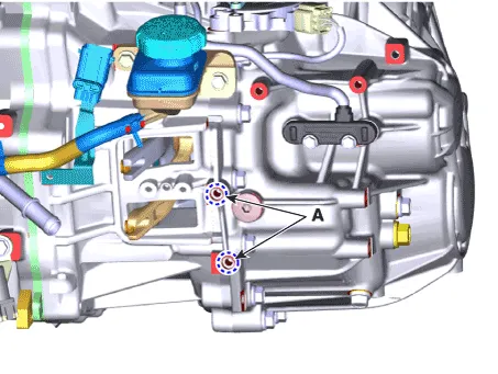
|
| •
| Perform the clutch touch point learning procedure using the GDS after replacing the clutch actuator assembly. 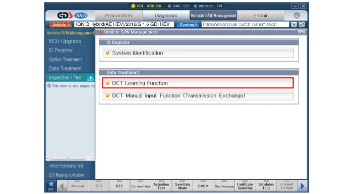
| •
| Even if you removed and reinstalled the clutch actuator, be sure to perform the touch point learning. |
| •
| If you have replaced the dual clutch assembly or clutch actuator, be sure to perform the touch point learning. |
|
|
|
| •
| If you replaced the dual clutch assembly or clutch actuator, be sure to perform wear compensation by referring to the following table.
Case
| Replaced Part
| Wear Compensation (Clutch Actuator)
| A
| Clutch actuator only
| Rewind the rod to adjust rod length
| B
| Dual Clutch assembly only
| Initialize the rod length.
| C
| Both dual clutch assembly and clutch actuator
| Initialize the rod length.
|
|
|
A. Rewinding the rod to adjust rod length (when only the clutch actuator is replaced)
| •
| Be sure to perform it when you have replaced the clutch actuator but reuse the dual clutch assembly. |
| •
| It is performed to adjust the rod length of a new clutch actuator to that of an old clutch actuator. |
|
| 1. | Remove the clutch actuator assembly. (Refer to Clutch Actuator Assembly - "Removal") |
| 2. | Disconnect the clutch actuator motor connector. | 1) | Remove the clutch actuator motor connector wiring bracket (A). 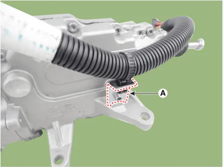
|
| 2) | Disconnect the clutch actuator motor connector (B). 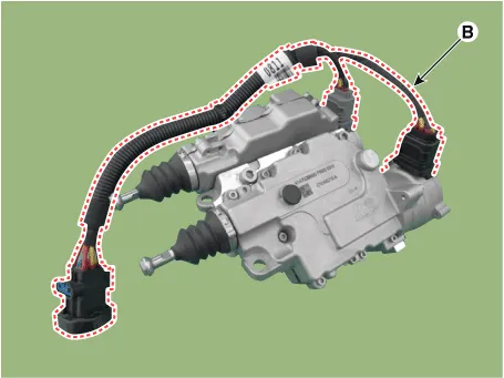
|
| •
| To measure the rod length of an old clutch actuator, perform the steps No. 3 - 4 of the following procedure. |
|
|
| 3. | Install the faulty clutch actuator (A) on special service tool (09430-F0100) and fix the actuator using nuts and bolts. 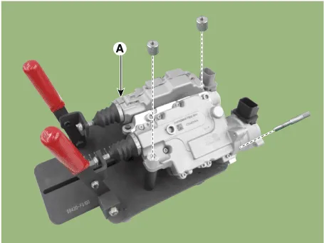
|
| 4. | Slightly pull the lever of the clutch actuator removed from the vehicle and measure the length of each old rod (C). Length of the old rod (C) : Length from the reference plane (A) to the end of the rod (B). |
| 2) | Clutch actuator 2 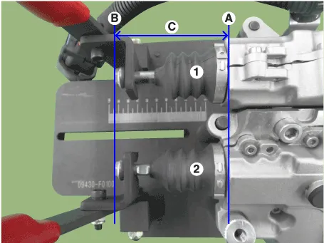
|
| •
| If the rod length is less than 57 mm (2.2441 in.) replace all of the dual clutch assembly, clutch actuator, and engagement bearing. |
|
|
| 5. | Remove the clutch actuator from the special service tool (09430-F0100). | •
| To match the rod length of a new clutch actuator with that of the clutch actuator removed from the vehicle, perform the steps No. 6 - 15 of the following procedure. |
|
|
| 6. | Install the faulty clutch actuator (A) on special service tool (09430-F0100) and fix the actuator using nuts and bolts.
|
| 7. | Fix the pull rod to hook (B) and then remove sealing rubber (A). 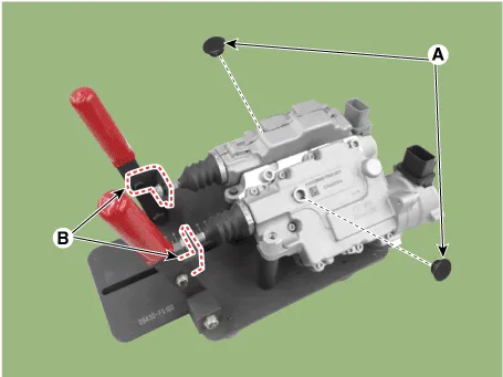
|
| 8. | Slightly pull the lever of the new clutch actuator and measure the length of each new rod (C). Length of the new rod (C) : Length from the reference plane (A) to the end of the rod (B). |
| 2) | Clutch actuator 2
|
|
| 9. | With the clutch actuator fixing jig (09430-F0100) (A) installed, stand the clutch actuator vertically. |
| 10. | After standing it vertically, remove the hook (B) from the rod. 
|
| 11. | Press the end part of rod (A) and release the pressing force when you see the nut bump (B). 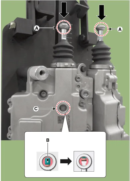
| •
| Light inside of the hole (C) and check the nut bump (B) inside of it. |
| •
| Repeat the operation if the nut bump (B) does not come down to the assembly hole position. |
| •
| The nut bump (B) can be moved up a little by sealing boot if the pressing force is released. |
|
|
| 12. | Insert a special tool (09430-C1300) (A) to a sealing rubber hole. Rotate the SST clockwise and adjust the length of the new clutch actuator's rod to the "length of old rod", which was measured at step No. 4. Increasing (+) rod length : Rotate counter-clockwise / once +0.25mm (+0.0009 in.) Shortening (-) rod length : Rotate clockwise / once -0.25mm (-0.0009 in.) |
| •
| Perform the same procedure for the opposite side rod. |
|
| •
| Be aware not to break the clutch actuator caused by break away inner parts when the SST over rotates clockwise. |
| •
| IIf the "length of the clutch actuator's new rod" is not adjusted to the "length of the old rod" measured at step No. 4, the DCT shift shock may occur or driving may be impossible. |
|
|
| 13. | With the clutch actuator fixing jig (09430-F0100) (A) mounted, maintain the level of the clutch actuator. |
| 14. | With the fixing jig (094320-F0100) levelled, install the hook (B) on the clutch actuator. 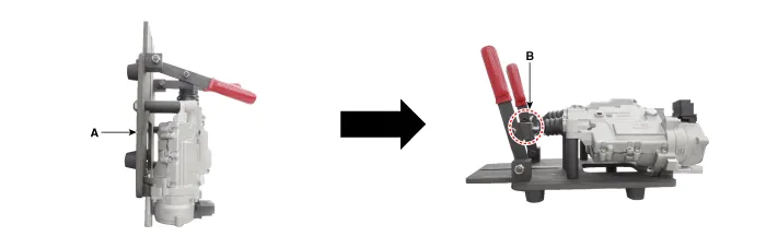
|
| 15. | Slightly pull the lever of the clutch actuator and check whether the "length of the rod which the final adjustment is finished" is same with the "length of the old rod" measured at step No. 4. Rod length (C) : Length from the reference plane (A) to the end of the rod (B). |
|
| 16. | Install the sealing rubber (A). 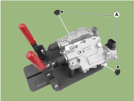
|
| 17. | Remove the clutch actuator assembly from the special tool (09430-F0100). |
B. Initializing the rod length (When only the dual clutch assembly is replaced or Both dual clutch assembly and clutch actuator is replaced)
| •
| Be sure to perform it when you have replaced the dual clutch assembly but reuse the clutch actuator. |
| •
| Perform the procedure when both the dual clutch assembly and clutch actuator are replaced. |
| •
| It is performed to adjust the rod length of an old clutch actuator to that of a new clutch actuator. |
|
| 1. | Remove the clutch actuator assembly. (Refer to Clutch Actuator Assembly - "Removal") |
| 2. | Install the faulty clutch actuator (A) on special service tool (09430-F0100) and fix the actuator using nuts and bolts.
|
| 3. | Fix the pull rod to hook (B) and then remove sealing rubber (A).
|
| 4. | Slightly pull the lever of the clutch actuator removed from the vehicle and measure length of each rod (C). If the length is shorter than the initialization length, you need to perform initialization. Rod length (C) : Length from the reference plane (A) to the end of the rod (B). (Initializ rod length : 82.0 - 83.0 mm (3.2283 - 32677 in.) |
| 2) | Clutch actuator 2
|
|
| 5. | Stand the clutch actuator vertically with SST (09430-F0100) (A) installed. |
| 6. | After standing it vertically, remove the hook (B) from the rod.
|
| 7. | Press the end part of rod (A) and release the pressing force when you see the nut bump (B).
| •
| Light inside of the hole (C) and check the nut bump (B) inside of it. |
| •
| Repeat the operation if the nut bump (B) does not come down to the assembly hole position. |
| •
| The nut bump (B) can be moved up a little by sealing boot if the pressing force is released. |
|
|
| 8. | Insert a special tool (09430-C1300) (A) to a sealing rubber hole. Rotate the SST counter-clockwise and adjust the length of the clutch actuator's rod. Increasing (+) rod length : Rotate counter-clockwise / once +0.25mm (+0.0098 in) Shortening (-) rod length : Rotate clockwise / once -0.25mm (-0.0098 in) |
| •
| Perform the same procedure for the opposite side rod. |
|
| •
| Be aware not to break the clutch actuator caused by break away inner parts when the SST over rotates clockwise. |
| •
| If the rod length is not initialized to 82.0 - 83.0 mm (3.2283 - 32677 in.) ( during initialization of wear compensation, DCT shift shock may occur or driving may be impossible. |
|
|
| 9. | With the clutch actuator fixing jig (09430-F0100) (A) mounted, maintain the level of the clutch actuator. |
| 10. | With the fixing jig (094320-F0100) levelled, install the hook (B) on the clutch actuator.
|
| 11. | Slightly pull the lever of the clutch actuator and check whether the "length of the rod which the final adjustment is finished" is same with the "rod's initialized length". Rod length (C) : Length from the reference plane (A) to the end of the rod (B). (Initializ rod length : 82.0 - 83.0 mm (3.2283 - 32677 in.) |
| 2) | Clutch actuator 2
|
|
| 12. | Install the sealing rubber (A).
|
| 13. | Remove the clutch actuator assembly from the special tool (09430-F0100). |
Other information:
C
Removal1.Disconnect the negative (-) battery terminal.2.Remove the front / rear bumper cover.(Refer to Body - "Front Bumper Cover")(Refer to Body - "Rear Bumper Cover")3.Disconnect the connector (A) from the parking assist sensor.4.Remove the sensor (A) by pulling out both ends of the sensor holder.


