Hyundai Ioniq (AE): Brake System / Stop Lamp Switch. Repair procedures
| Removal |
| 1. | Turn ignition switch OFF and disconnect the negative (-) battery cable. |
| 2. | Remove the lower crash pad. (Refer to Body - "Crash Pad") |
| 3. | Remove the knee airbag. (Refer to Rstraint - "Air Bag Module") |
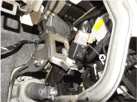
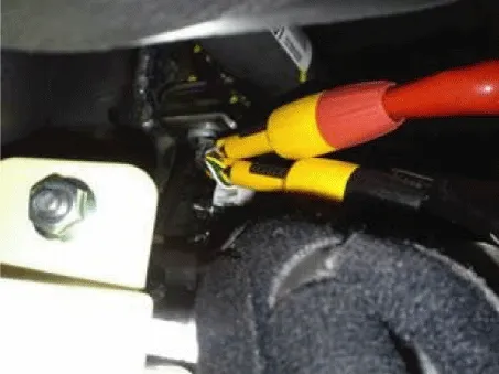
| 4. | Disconnect the stop lamp switch connector (A).
|
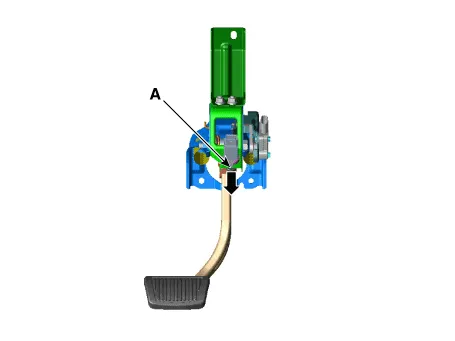
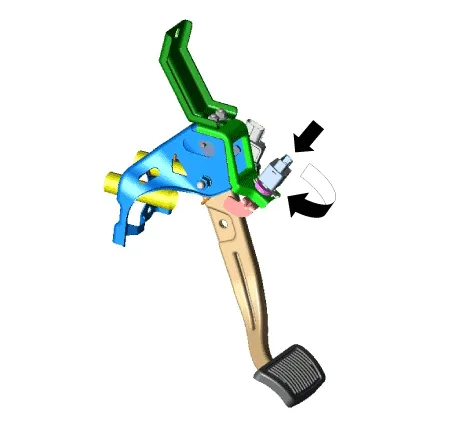
| 5. | Pull the locking plate (A) as indicated by the arrow.
|
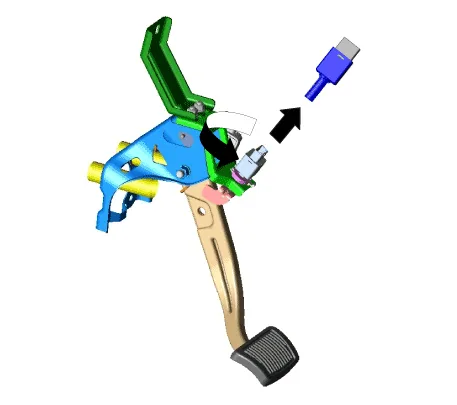
| 6. | Turn stop lamp switch 45° counterclockwise and remove it.
|
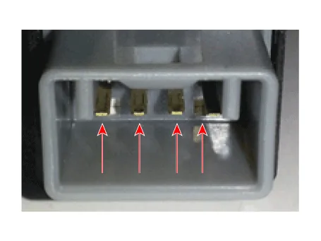
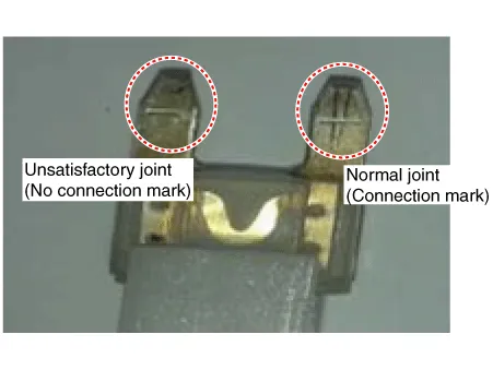
| 7. | Inspect a removed stop lamp switch along the below procedures.
|
| Installation |
| 1. | Fix the brake pedal arm and insert fully the stop lamp switch as hiding contact part. Turn stop lamp switch 45° clockwise and install it.
|
| 2. | Assemble locking plate (A) by pushing.
|

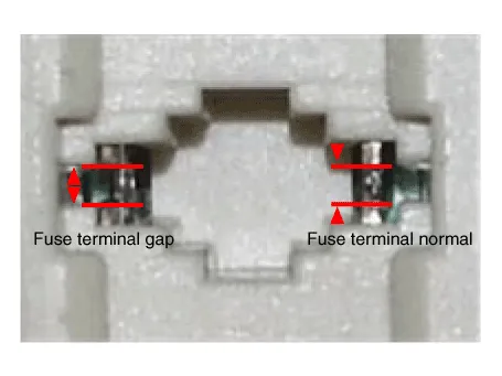
| 3. | Confirm the gap between stop lamp switch and bracket.
|

| 4. | Connect the stop lamp switch connector.
|
| 5. | Remove the knee airbag. (Refer to Rstraint - "Air Bag Module") |
| 6. | Install the lower crash pad. (Refer to Body - "Crash Pad") |
| 7. | Connect the negative (-) battery cable. |
| Adjustment |
| 1. | Turn ignition switch OFF and disconnect the negative (-) battery cable. |
| 2. | Remove the lower crash pad. (Refer to Body - "Crash Pad") |
| 3. | Remove the knee airbag. (Refer to Rstraint - "Air Bag Module") |
| 4. | Confirm the gap between stop lamp switch and bracket.
|

| 5. | If the gap between stop lamp switch and bracket is not 1.0 - 2.0 mm (0.04 - 0.08 in), check the mounting clip and other part of around stop lamp. |
| 6. | If there is normal, remove the stop lamp switch and then install again. |
| Inspection |
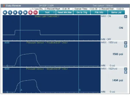
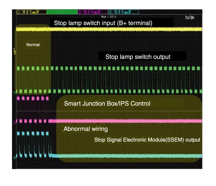
| 1. | Analyze GDS data and confirm if there is anything wrong with the stop lamp switch.
|
Schematic DiagramSystem Circuit DiagramTerminal Function Teminal Description 1IGN12Engine Control Module (ECM)3B+4Stop Lamp
Troubleshooting1. Part diagnosis Items Cause Symptom Switch fuse Faulty fuse connection, Damaged fuse – DTC Code : P0504– Symptom : Shifting gear trouble, Starting failure, Cruise control function cancelation trouble, EPB function cancelation trouble, Stop lamp lighting trouble, ESP OFF light illuminated.
Other information:
Hyundai Ioniq (AE) 2017-2022 Service & Repair Manual: Front Radar Unit. Description and operation
DescriptionThe smart cruise control unit is installed on the front right side of the chassis. A radar sensor is embedded in the front section of the unit. This sensor detects vehicles and objects in front of the vehicle. The radar sensor can detect up to 64 objects ahead of a vehicle.
Hyundai Ioniq (AE) 2017-2022 Service & Repair Manual: Rear Corner Radar Unit. Repair procedures
Removal1.Disconnect the negative (-) battery terminal.2.Remove the rear bumper.(Refer to Body - "Rear Bumper")3.Remove the rear corner radar unit (A) after loosening the mounting nuts. • Take care not to separate the bracket from rear bumper when removing the rear corner radar sensor.
Categories
- Manuals Home
- Hyundai Ioniq Owners Manual
- Hyundai Ioniq Service Manual
- Maintenance
- Hybrid Vehicle Engine Compartment
- If the 12 Volt Battery is Discharged (Hybrid Vehicle)
- New on site
- Most important about car
