
Hyundai Ioniq (AE): Cooling System / Thermostat. Repair procedures
| Removal and Installation |
|

| 1. | Drain the engine coolant so its level is below thermostat. (Refer to Cooling System - "Coolant") |
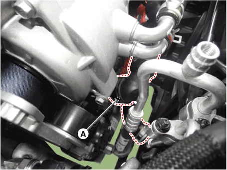
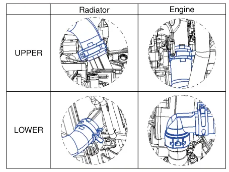
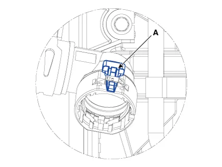
| 2. | Disconnect the radiator lower hose (A).
|
| 3. | Remove the water inlet fitting (A).
|
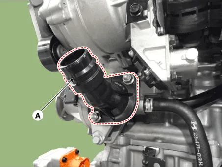
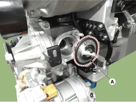
| 4. | Remove the thermostat (A).
|
| 5. | Install in the reverse order of removal. |
| 6. | Fill the radiator with coolant and check for leaks. (Refer to Cooling System - "Coolant") |
| 7. | Start engine and check for leaks. |
| 8. | Recheck the coolant level. |
| Inspection |
| 1. | Immerse the thermostat in water and gradually heat the water.
|
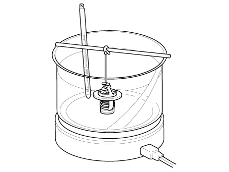
| 2. | Check the valve opening temperature.
If the valve opening temperature is not as specified, replace the thermostat. |
| 3. | Check the valve lift.
If the valve lift is not as specified, replace the thermostat. |
Components1. Water inlet fitting2. Thermostat
Troubleshooting Symptoms Possible Causes Remedy Coolant leakage• From the thermostat gasketCheck the mounting bolts• Check the torque of the mounting bolts• Retighten the bolts and check leakage again.
Other information:
Hyundai Ioniq (AE) 2017-2022 Service & Repair Manual: Repair procedures
Self Diagnosis1.Self-diagnosis process. • When operating the self-diagnostics, the below fault (self-diagnostics code) will blink at 0.5 seconds interval on the temperature display settings (driver's side only) and the remaining symbols are OFF .
Hyundai Ioniq (AE) 2017-2022 Service & Repair Manual: High voltage shut-off procedures
High Voltage Shut-off Procedures • Be sure to read and follow the "General Safety Information and Caution" before doing any work related with the high voltage system. Failure to follow the safety instructions may result in serious electrical injuries.
Categories
- Manuals Home
- Hyundai Ioniq Owners Manual
- Hyundai Ioniq Service Manual
- Components and components location
- Hybrid Vehicle Engine Compartment
- Jump Starting
- New on site
- Most important about car
