Hyundai Ioniq (AE): AHB(Active Hydraulic Boost) System / Components and components location
| Components |
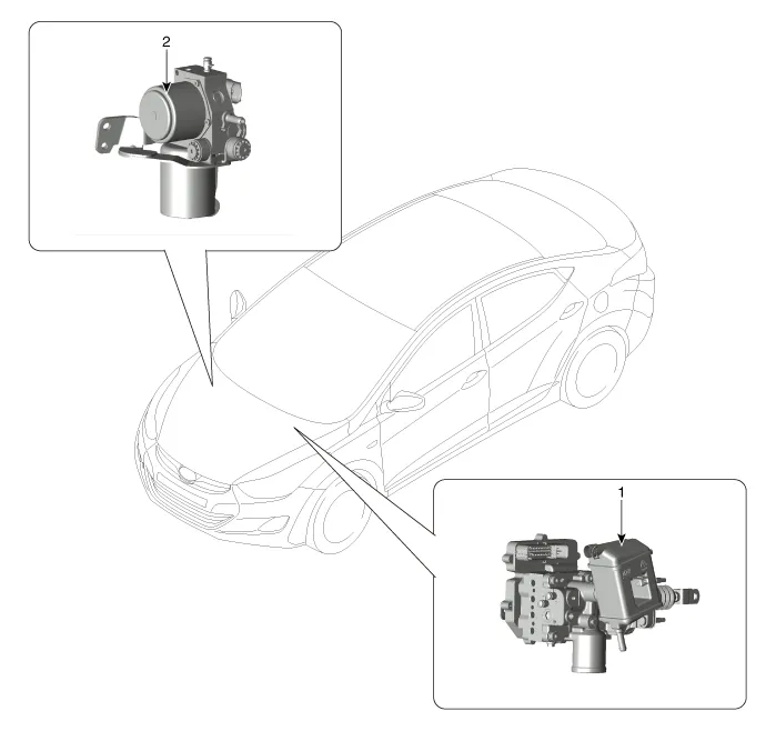
| 1. Intergrated Brake Actuation Unit | 2. Pressure Source Unit |
DescriptionRegeneration Brake SystemDuring deceleration or braking of an electric vehicle or HEV, the drive motor acts as an alternator and charges the battery by converting the vehicle’s kinetic energy generated during braking into electrical energy.
Terminal FunctionIBAU Connector Input / Output No Description No Description 1E/R Fuse & Relay Box(Multi Fuse - AHB)24Electric Parking Brake Switch(Auto Hold Swutch)2PSU Motor (+)25-3-26Parking Brake Switch4Shield Cable Ground27Rear Wheel Sensor LH (SIG)5E/R Fuse & Relay BoxPSU Motor (GND)28Front Wheel Sensor LH (SIG)6Brake Pedal Module (PDT PWR) 29Driver Door Switch7Brake Pedal Module (PDF PWR)30E/R Fuse & Relay Box(Multi Fuse - AHB 2)8E/R Fuse & Relay Box(Stop Signal Electronic Module)31Brake Pedal Module (PDF GND)9-32-10Brake Pedal Module (PDT GND)33Rear Wheel Sensor LH (VCC)11Shield Cable Ground34Rear Wheel Sensor RH (VCC)12-35-13PSU Motor (-)36Brake light switch14Ground 37-15-38C-CAN (High)16Crash Pad Switch (ESC OFF Switch)39C-CAN (Low)17Front Wheel Sensor LH (VCC)40Vehicle Speed :Smart Key Control Module, PCM18Front Wheel Sensor RH (VCC)41-19P-CAN (High)42Front Wheel Sensor RH (SIG)20P-CAN (Low)43Rear Wheel Sensor RH (SIG)21ESS Drive44Stop Lamp Switch22Brake Pedal Module (PDT SIG)45- 23Brake Pedal Module (PDF SIG)46Ground (GE06)
Other information:
Hyundai Ioniq (AE) 2017-2022 Service & Repair Manual: Repair procedures
Service Point Target Auto Calibration (SPTAC)When you need calibration :– Front view camera is removed and mounted– Replace front view camera with a new one – Windshield glass changed– Front view camera coupler of the windshield glass is deformedService Point T
Hyundai Ioniq (AE) 2017-2022 Service & Repair Manual: Description and operation
Cruise ControlThe cruise control system is engaged by the cruise "ON/OFF" main switch located on right of steering wheel column. The system has the capability to cruise, coast, accelerate and resume speed.It also has a safety interrupt, engaged upon depressing brake or shifting select lever.
Categories
- Manuals Home
- Hyundai Ioniq Owners Manual
- Hyundai Ioniq Service Manual
- Theft-alarm System
- General Information
- Hybrid Vehicle Engine Compartment
- New on site
- Most important about car
