Hyundai Ioniq: Dual Clutch Transmission Control System / DCT Control Module (TCM). Repair procedures
Hyundai Ioniq (AE) 2017-2025 Service Manual / DCT(Dual Clutch Transmission) System / Dual Clutch Transmission Control System / DCT Control Module (TCM). Repair procedures
| Inspection |
| Transmission Control Module (TCM) Inspection Procedure |
| 1. | Inspecting TCM ground circuit: Measure the resistance between the TCM and chassis ground. (Check the terminal connected to the chassis ground while using the back of the harness connector as the base point for TCM.)
|
| 2. | Inspecting the TCM connector: Disconnect the TCM connector and visually inspect to see whether there is a bend on the ground terminal of the harness connector. Also visually check the connection pressure. |
| 3. | If no problem is found during inspection in step 1 and step 2, then the problem is with the TCM itself. In this case, replace the TCM and inspect the vehicle again. |
| 4. | Re-inspecting TCM: Install the TCM that was determined to have malfunctioned from step 3 in another vehicle. Reset the error code and then check the operation in that vehicle. If the vehicle operates without any problems, then inspect the first vehicle with the initial problem again. |
| Removal |
| 1. | Turn ignition switch OFF and disconnect the battery negative (-) terminal. |
| 2. | Disconnect the TCM connector (A).
|
| 3. | Remove the TCM from the vehicle after loosen the bolts (A-4ea).
|
| Installation |
| 1. | Install in the reverse order of removal.
|

 DCT Control Module (TCM). Schematic diagrams
1. TCM Connector and Terminal Function2. TCM Terminal FunctionConnector [A]
Pin
Description
Pin
Description
1Clutch Actuator (Clutch Motor 1 (ODD)_Phase V)17-2Clutch actuator (Clutch Motor 2 (EVEN) Phase V)18Clutch Actuator (Clutch Motor 1 (ODD)_HALL 1)3Select Actuator (Select Solenoid 2 (EVEN)_Ground)19Clutch Actuator (Clutch Motor 1 (ODD)_Sensor Supply)4Select Actuator (Select Solenoid 1 (ODD) Push)20Select Actuator (Select Solenoid 1 (ODD)_Sensor Sensor Supply)5Clutch Actuator (Clutch Motor 1 (ODD)_Phase U)21Select Actuator (Select Solenoid 2 (EVEN)_Sensor Sensor Supply)6Clutch Actuator (Clutch Motor 2 (EVEN)_Phase U)22Select Actuator (Select Solenoid 2 (EVEN)_Sensor Ouput)7Select Actuator (Select Solenoid 1 (ODD)_Ground)23Clutch Actuator (Clutch Motor 2 (EVEN)_HALL 2)8Select Actuator (Select Solenoid 2 (EVEN)_ Pull)24Clutch Actuator (Clutch Motor 2 (EVEN)_HALL 3)9Clutch Actuator (Clutch Motor1 (ODD)_Phase W)25Clutch Actuator (Clutch Motor 2 (EVEN)_Ground)10Clutch Actuator (Clutch Motor 2 (EVEN)_Phase W)26Select Actuator (Select Solenoid 1 (ODD)_Sensor Output)11Select Actuator (Select Solenoid 1 (ODD) Pull)27-12Select Actuator (Select Solenoid 2 (EVEN) Push)28Clutch Actuator (Clutch Motor 2 (EVEN)_HALL 1)13Clutch Actuator (Clutch Motor 1 (ODD)_HALL 2)29Clutch Actuator (Clutch Motor 2 (EVEN)_Sensor Supply)14Clutch Actuator (Clutch Motor (ODD)_HALL 3)30Select Actuator (Select Solenoid 1 (ODD)_Sensor Ground)15Clutch Actuator (Clutch Motor 1 (ODD)_Ground)31Select Actuator (Select Solenoid 2 (EVEN)_Sensor Ground)16-32-Connector [B]
Pin
Description
Pin
Description
1-35-2-36-3ON / START Input37-4Paddle Shift (Up) Switch signal38-5Inhibitor Switch "P" Input signal39-6Inhibitor Switch "R" Input signal40-7Inhibitor Switch "D" Input signal41Shift Actuator (Shift Motor 2 (EVEN) _HALL 2)8Sports mode "Down" shift42Shift Actuator (Shift Motor 2 (EVEN) _HALL 3)9Clutch Speed Sensor (EVEN) Ground43Inhibitor Switch "M" Input signal10-44CAN1 Communication Port1 High11-45CAN1 Communication Port1 Low12-46-13Shift Actuator (Shift Motor 1 (ODD) _HALL 2)47-14Shift Actuator (Shift Motor 1 (ODD) _HALL 3)48Flex ray High (BP)15-49Input Speed Sensor Supply 1 (ODD)16-50Input Speed Signal 1 (ODD)17Battery Power Low VBD 51-18Paddle Shift Down signal52-19Shift Lever Select Switch53-20Inhibitor Switch "N" Input signal54Shift Actuator (Shift Motor 2 (EVEN) _Sensor Supply)21Sports mode "Up" shift55Shift Actuator (Shift Motor 2 (EVEN) _HALL 1)22-56Shift Actuator (Shift Motor 2 (EVEN) _Sensor Ground)23Input Speed Sensor Supply 2 (EVEN)57Power Ground 1 for High Current Modules245V spare Sensor Supply output58Power Ground 2 for High Current Modules25-59Shift Actuator (Shift Motor 2 (EVEN)_Phase W)26Shift Actuator (Shift Motor 1 (Odd)_Sensor Supply)60Shift Actuator (Shift Motor 1 (ODD)_Phase W)27Shift Actuator (Shift Motor 1 (ODD)_HALL 1)61 Power Ground 3 for High Current Modules28Select Actuator (Shift Motor 1 (ODD)_Sensor Ground)62-29-63Shift Actuator (Shift Motor 2 (EVEN)_Phase V)30CAN2 Communication Port2 High64Shift Actuator (Shift Motor 1 (ODD)_Phase V)31CAN2 Communication Port2 Low65Motor Sensor Supply Voltage 1 from Direct Battery32-66Motor Sensor Supply Voltage 2 from Direct Battery33-67Shift Actuator (Shift Motor 2 (EVEN)_Phase U)34Flex ray bus, BM68Shift Actuator (Shift Motor 1 (ODD)_Phase U)3...

Other information:
Hyundai Ioniq (AE) 2017-2025 Owner's Manual: Detecting sensor
The sensors are located inside the rear bumper. Always keep the rear bumper clean for the proper operation of the system. Warning message Blind-Spot Collision Warning (BCW) system disabled. Radar blocked This warning message may appear when : - One or both of the sensors on the rear bumper is blocked by dirt or snow or a foreign object...
Hyundai Ioniq (AE) 2017-2025 Service Manual: Specifications
SpecificationSafety Plug▷ Specification Item Specification Rated Voltage (V) 400 Rated Current (A) 80 Fuse Rated Current (A) 125 Fuse Melting Time Rated Current x 110% Min...
Categories
- Manuals Home
- 1st Generation Ioniq Owners Manual
- 1st Generation Ioniq Service Manual
- Jump Starting
- Checking the Coolant Level
- How to Disconnect Normal Charger
- New on site
- Most important about car
Air Bag Warning Labels
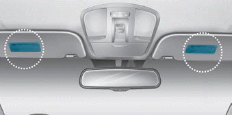
Air bag warning labels, required by the U.S. National Highway Traffic Safety Administration (NHTSA), are attached to alert the driver and passengers of potential risks of the air bag system. Be sure to read all of the information about the air bags that are installed on your vehicle in this Owners Manual.

Copyright © 2025 www.hioniqae.com