Hyundai Ioniq (AE): Hybrid Motor Cooling System / Radiator. Repair procedures
Hyundai Ioniq (AE) 2017-2022 Service & Repair Manual / Hybrid Motor System / Hybrid Motor Cooling System / Radiator. Repair procedures
| Removal |
| 1. | Remove the 12 V battery (-) cable. |
| 2. | Remove the undercover. (Refer to Engine Mechanical System - "Engine Room Undercover".) |
| 3. | Drain the coolant from the hybrid cooling system. (refer to Hybrid Motor Cooling System - "Coolant".) |
| 4. | Remove the engine radiator. (Refer to Engine Mechanical System - "Radiator".) |
| 5. | Remove the front bumper. (Refer to Body - "Front Bumper".) |
| 6. | Use the recovery / reproduction/charging device to recover the coolant. (Refer to Heater and Air Conditioner-"Maintenance Procedure".) |
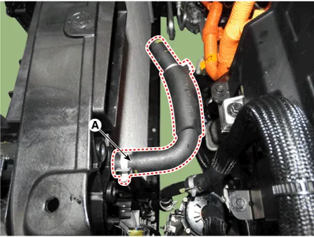
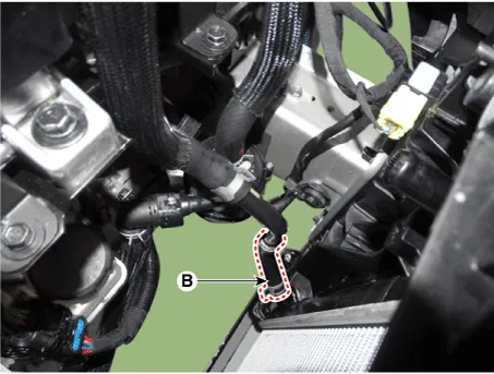
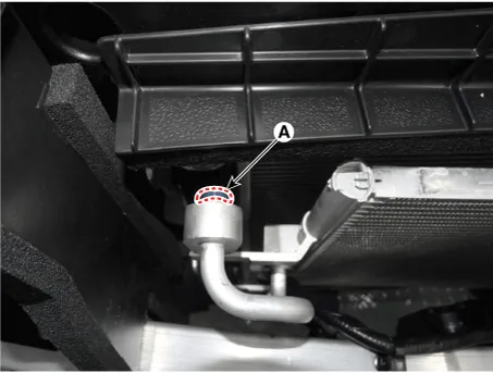
| 7. | Remove the hoses (A) and (B) from the electric radiator.
|

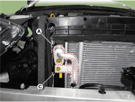
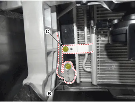
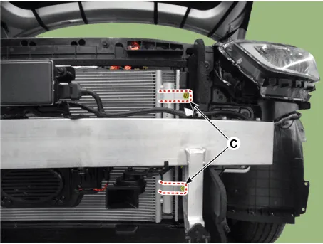
| 8. | Remove the coolant line (A) and (B). |
| 9. | Unscrew the condenser fixing bolt (C).
|
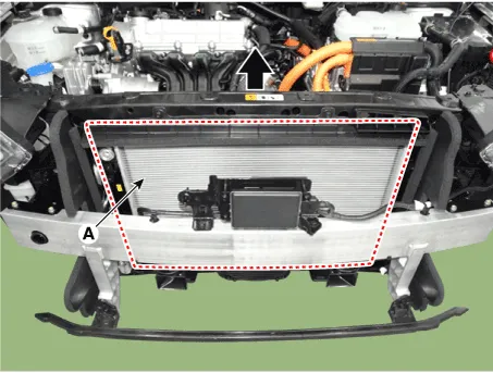
| 10. | Remove the electric radiator (A).
|
| Installation |
| 1. | To install, reverse the removal procedure. |
Component location1. HPCU (Hybrid Power Control Unit)(LDC+MCU+HCU+Reservoir)2. Hybrid drive motor3. Hybrid starter generator (HSG)4. Electrical radiator5.
Component location1. Reservoir2. Hybrid drive motor3. Hybrid starter generator (HSG)4. Electrical radiator5. Electric water pump (EWP)
Other information:
Hyundai Ioniq (AE) 2017-2022 Service & Repair Manual: Repair procedures
Self Diagnosis1.Self-diagnosis process. • When operating the self-diagnostics, the below fault (self-diagnostics code) will blink at 0.5 seconds interval on the temperature display settings (driver's side only) and the remaining symbols are OFF .
Hyundai Ioniq (AE) 2017-2022 Service & Repair Manual: Specifications
S
Categories
- Manuals Home
- Hyundai Ioniq Owners Manual
- Hyundai Ioniq Service Manual
- Jump Starting
- Suspension System
- Engine Clutch System
- New on site
- Most important about car

Copyright © 2026 www.hioniqae.com - 0.0163