Hyundai Ioniq (AE): Cylinder Block / Piston and Connecting Rod. Repair procedures
Hyundai Ioniq (AE) 2017-2022 Service & Repair Manual / Engine Mechanical System / Cylinder Block / Piston and Connecting Rod. Repair procedures
| Disassembly |
|

|

|

| 1. | Remove the engine assembly from the vehicle. (Refer to Engine and Transaxle Assembly - "Engine and Transaxle Assembly") |
| 2. | Remove the transaxle assembly from the engine assembly. (Refer to Double Clutch Transmission (DCT) System - "Double Clutch Transmission (DCT)") |
| 3. | Remove the flywheel. (Refer to Cylinder Block - "Flywheel") |
| 4. | Remove the rear oil seal. (Refer to Cylinder Block - "Rear Oil Seal") |
| 5. | Install the engine to engine stand for disassembly. |
| 6. | Remove the intake manifold. (Refer to Intake and Exhaust System - "Intake Manifold") |
| 7. | Remove the exhaust manifold. (Refer to Intake and Exhaust System - "Exhayst Manifold") |
| 8. | Remove the hybrid starter generator (HSG). (Refer to Hybrid Motor System - "Hybrid Starter Generator (HSG)") |
| 9. | Remove the timing chain. (Refer to Timing System - "Timing Chain") |
| 10. | Remove the cylinder head assembly. (Refer to Cylinder Head Assembly - "Cylinder Head") |
| 11. | Remove the thermostat. (Refer to Cooling System - "Thermostat") |
| 12. | Remove the EGR cooler. (Refer to Intake and Exhaust System - "EGR Cooler") |
| 13. | Remove the A/C compressor. (Refer to Heating, Ventilation Air conditioning -"Compressor") |
| 14. | Remove the knock sensor. (Refer to Engine Control / Fuel System - "Knock Sensor") |
| 15. | Remove the oil pan and oil screen. (Refer to Lubrication System - "Oil Pan") |
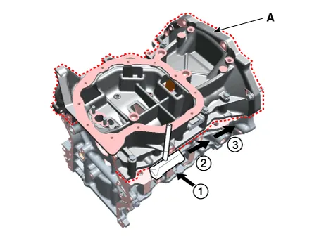
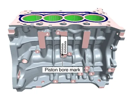
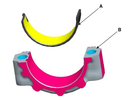
| 16. | Remove the ladder frame (A).
|
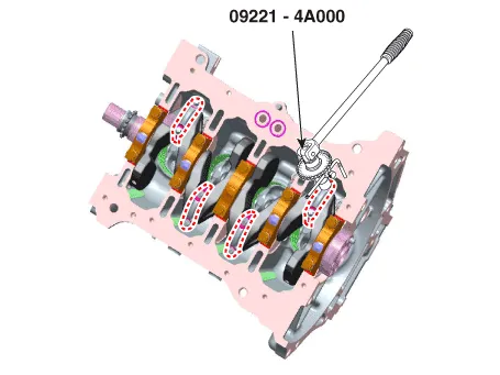
| 17. | Check the connecting rod side clearance. |
| 18. | Check the connecting rod cap oil clearance. |
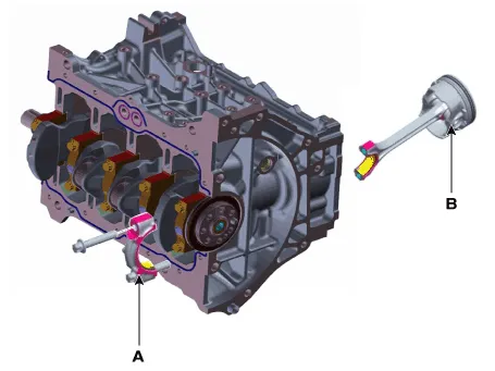
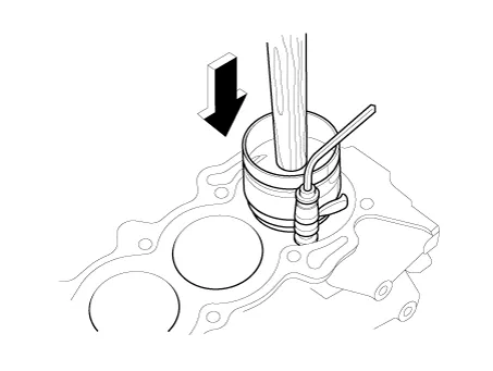
| 19. | Remove the piston and connecting rod assemblies.
|

| 20. | Check fit between piston and piston pin. Try to move the piston back and forth on the piston pin. If any movement is felt, replace piston and piston pin as a set. |
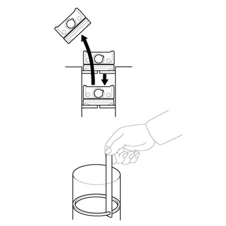
| 21. | Remove the piston rings.
|
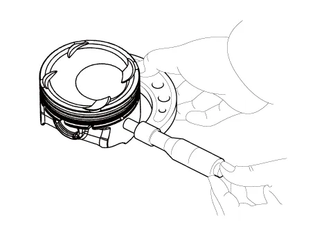
| 22. | Remove the connecting rod from the piston. Using a press, remove the piston pin from the piston. |
| Inspection |
Connecting Rod
| 1. | Check the connecting rod side clearance. Using a feeler gauge, measure the end play while moving the connecting rod back and forth.
|
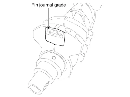
| 2. | Check the connecting rod bearing oil clearance.
| |||||||||||||||||||||||||||||||||||||||||||||||||||||||||||||||||||||||||||||||||||||||||||||||||||||||||||||||
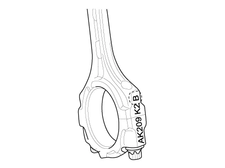

| 3. | Check the connecting rods.
|
Piston
| 1. | Clean the piston
|
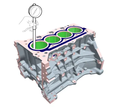
| 2. | Check the piston-to-cylinder clearance by calculating the difference between the cylinder bore inner diameter and the piston outer diameter.
|
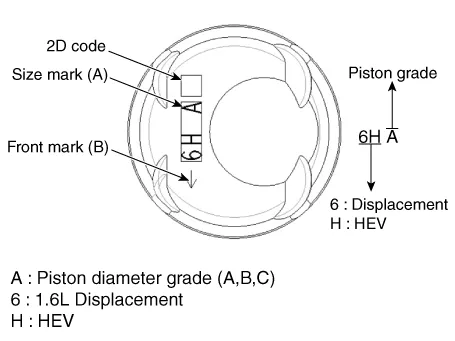
| 3. | Select the piston matching with cylinder bore class.
|
Piston Rings
| 1. | Inspect the piston ring side clearance. Using a feeler gauge, measure the clearance between new piston ring and the wall of the ring groove.
If the clearance is greater than maximum, replace the piston. |
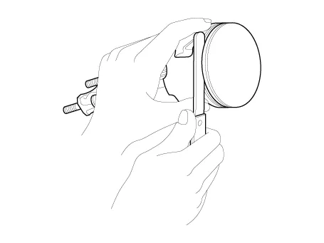
| 2. | Inspect piston ring end gap. To measure the piston ring end gap, insert a piston ring into the cylinder bore. Position the ring at right angles to the cylinder wall by gently pressing it down with a piston. Measure the gap with a feeler gauge. If the gap exceeds the service limit, replace the piston ring. If the gap is too large, recheck the cylinder bore diameter against the wear limits. If the bore is over the service limit, the cylinder block must be replaced.
|
Piston Pins
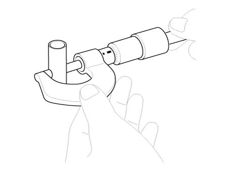
| 1. | Measure the diameter of the piston pin.
|
| 2. | Measure the piston pin-to-piston clearance.
|
| 3. | Check the difference between the piston pin outer diameter and the connecting rod small end inner diameter.
|
| Reassembly |
|
| 1. | Assemble the piston and connecting rod.
|

| 2. | Install the piston rings.
|

| 3. | Install the connecting rod bearings.
|
| 4. | Install the piston and connecting rod assemblies.
|
| 5. | Check the connecting rod bearing caps oil clearance. |
| 6. | Check the connecting rod end play. |
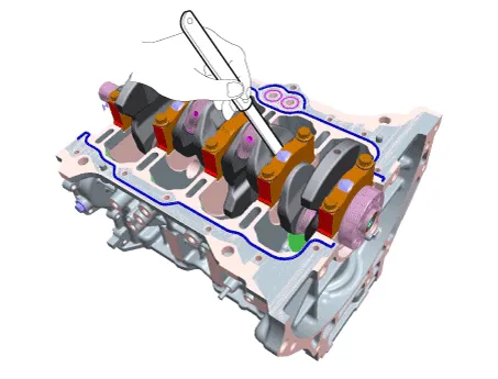
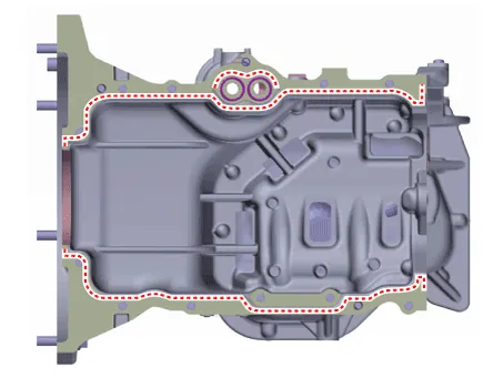
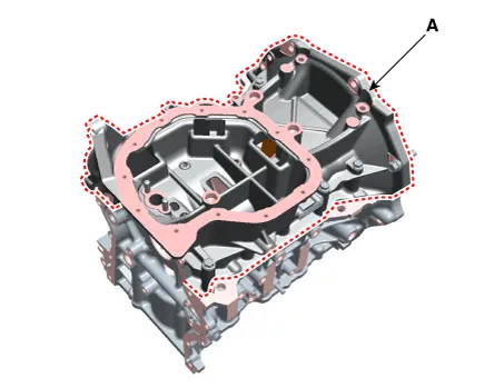
| 7. | Install the ladder frame
|
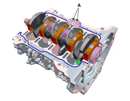
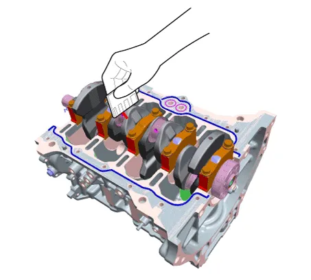
| 8. | Install the ladder frame (A).
|
| 9. | Assemble the other parts in the reverse order of disassembly. |
Components1. Piston ring2. Piston3. Piston pin4. Connecting rod5. Connecting rod upper bearing6. Connecting rod lower bearing7. Connecting rod bearing cap
Components1. Thrust bearing2. Main bearing (Upper)3. Crankshaft4. Main bearing (Lower)5. Main bearing cap
Other information:
Hyundai Ioniq (AE) 2017-2022 Service & Repair Manual: emperature Control Actuator. Description and operation
DescriptionThe temperature control actuator is located at the heater unit. It regulates the temperature by the procedure as follows. The signal from the control unit adjusts the position of the temperature door by operating the temperature switch. Then the temperature will be regulated by the hot/cold air ratio decided by the position of the temper
Hyundai Ioniq (AE) 2017-2022 Service & Repair Manual: emperature Control Actuator. Specifications
S
Categories
- Manuals Home
- Hyundai Ioniq Owners Manual
- Hyundai Ioniq Service Manual
- Checking the Coolant Level
- Maintenance
- Body (Interior and Exterior)
- New on site
- Most important about car

Copyright © 2026 www.hioniqae.com - 0.0207